48
Screw-less Clamp Terminals Section 4-2
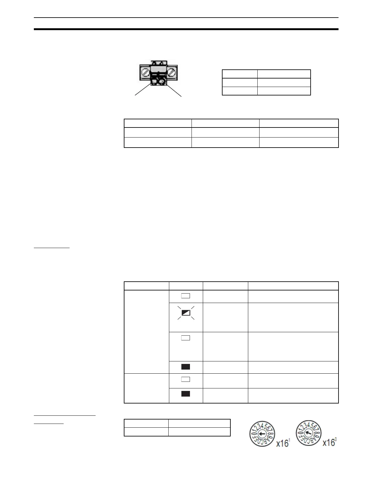
(3) Power Supply Connector
The communications and Unit power supply is connected to this connector.
Applicable Ferrules
(4) Communications Indicators: MS and NS
These indicators show the Unit communications status and network commu-
nications status.
(5) and (6) Terminal Blocks 1 and 2
The input devices and input power supply are connected to these terminal
blocks.
(7) and (8) Input Indicators
These indicators show the ON/OFF status of the inputs and the error status of
connected devices.
Indicators
Communications
Indicators
Refer to 3-1-3 Communications Indicators.
I/O Indicators The meanings of the input indicators are given in the following table.
Setting the Node
Address
The rotary switches are used to set the lower digits of the IP address.
Rotary Switch Settings
00 hex: BOOTP or tool setting enabled (factory setting)
Manufacturer Model Applicable wire size
Phoenix Contact AI-0.5-10
0.5 mm
2
(AWG 20)
Nihon Weidmuller H 0.5/16 D
0.5 mm
2
(AWG 20)
24 V DC
0 V DC
Terminal Specification
+ 24 V DC
− 0 V DC
Indicator name Status Color Meaning (main error)
0 to 15 Yellow Lit yellow when input is ON.
Red Flashing red when the load is dis-
connected.
Automatically reset when the load
is connected.
Red Lit red when the load is short-cir-
cuited.
Automatically reset when the
short-circuit is removed.
OFF Not lit when input is OFF.
I/O Green Lit green when I/O power is being
supplied.
OFF Not lit when I/O power is not being
supplied.
Setting method Two hexadecimal digits
Setting range 01 to FE
 Loading...


