67
Environment-resistive Slave Units Section 5-2
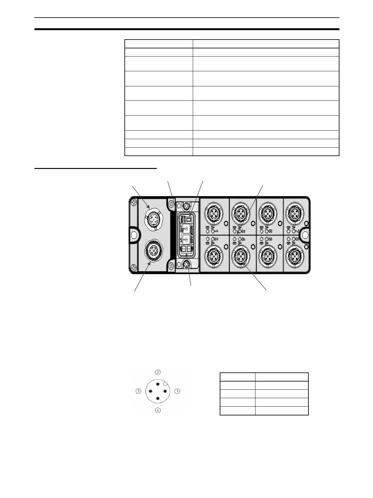
Component Names and Functions
(1) Rotary Switches
These switches are used to set the node address.
(2) Ethernet Connector
The network communications cable is connected to this connector.
This is a Smart-click D-coding M12 connector (connector that locks easily with
1/8 of a turn).
(3) Power Supply Connector
The power supply is connected to this connector.
This is a Smart-click D-coding M12 connector (connector that locks easily with
1/8 of a turn).
Output indicators LEDs (yellow)
Power supply short-circuit
protection
Operates when output current is exceeded.
Disconnection detection Operates at current consumption of 3 mA/point max. (Not
detected at 3 mA or less.)
Output handling for com-
munications errors
Select either hold or clear from Network Configurator.
Current consumption Communications power supply (including internal cir-
cuits): 120 mA max.
Connection forms M12 connector: Smart Click (connectors that lock easily
with 1/8 of a turn)
Mounting 35-mm DIN Track mounting
Weight 435 g max.
Standard accessories None
Item Specification
(1)
(2)
(3)
(4)
(5)
(6)
(7)
Pin Signal
1TD+
2 RD+
3TD−
4RD−
 Loading...


