4-13
4 Screen Creation
NB-series Programmable Terminals Startup Guide Manual(V109)
4-4 Screen Creation
4
4-4 Screen Creation
This part describes how to create screens displayed on NB7W.
[1 Wait] is the first display screen in the garage door control system. The screen will be displayed with
the lower limit LS ON.
Configure functions below:
• Level Meter component, indicating numbers of headlights flashing detected by the sensors in forms
of graphics.
• Bit Button components, allocated to [Open], [Stop] and [Close] garage door operations respectively.
• Bit Button component, for accessing the maintenance screen. The component turns ON when the
button is pressed for 3 seconds.
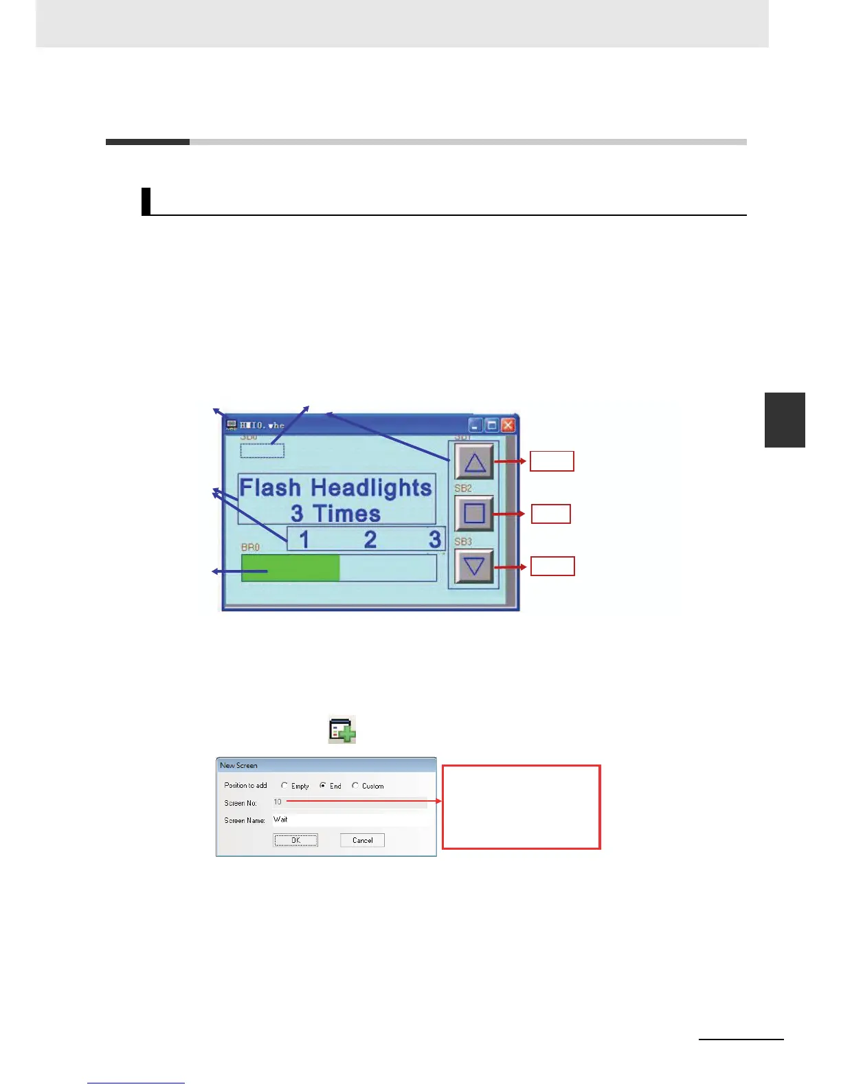
The whole screen is shown below. The following objects must be created and configured:
a Screen b Bit Button components c Texts d Level Meter component
z Screen
Start the following procedures after the NB7W operation is set.
1
Select [Add Screen] from the toolbar. Input “Wait” at the screen name area.
[1 Wait]
a
c
d
b
Use the vector graphic: Up.vg
Address: W_bit 1.00
Use the vector graphic: Middle.vg
Address: W_bit 1.01
Use the vector graphic: Down.vg
Address: W_bit 1.02
[Open]
[Stop]
[Close]
The initial design screen No. is 0,
named “Frame0”, when user
added a new frame, the screen
No. start from 10 by default.
Frame 1 to 9 are default frames
for the system.

 Loading...


