6.Communications Settings
8
6. Communications Settings
This section describes the parameters and device variables that are all defined in this guide.
6.1. EtherCAT Connection Parameter
The following parameter is required to connect the Controller and the Slave Terminal via
EtherCAT.
Slave Terminal setting
Node address 1
The address is set using the hardware switches on the
Slave Terminal.
6.2. IO-Link Connection Parameters
The following parameters are required to connect the IO-Link Master Unit and the Signal
Tower via IO-Link.
In this guide, the Signal Tower is connected to Port 1 on the IO-Link Master Unit.
IO-Link Master Unit setting
Port1 IO-Link Device Configuration Data / Process data in length
Port1 IO-Link Device Configuration Data / Process data out length
Port1 IO-Link Device Configuration Data / Master Control
*1 The process data length of the Signal Tower is "6 byte / 0 byte (input from master / output
to master)"; however, in this guide, the default value (2 bytes) is used for the process data
in length for Port 1 on the IO-Link Master Unit, which is related to the process data length
"0 byte (output to master)" of the Signal Tower.
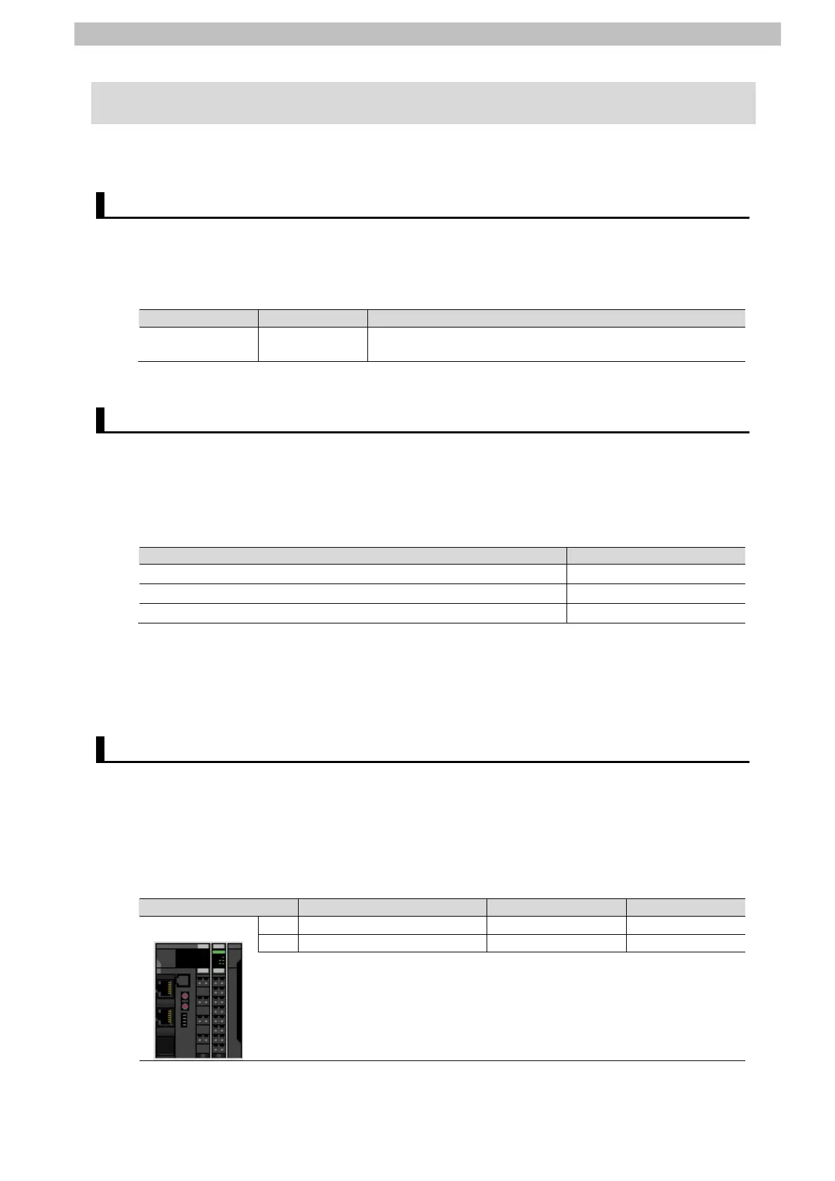
6.3. Slave Terminal Configuration and Device Names
The Slave Terminal configuration and device names are shown below.
The default values are used for the device names. For slave units, the default device names
are "E" followed by a serial number starting from "001". For NX Units, the default device
names are "N" followed by a serial number starting from "1".
Slave Terminal configuration and device names

 Loading...


