7.IO-Link Connection Procedure
39
21
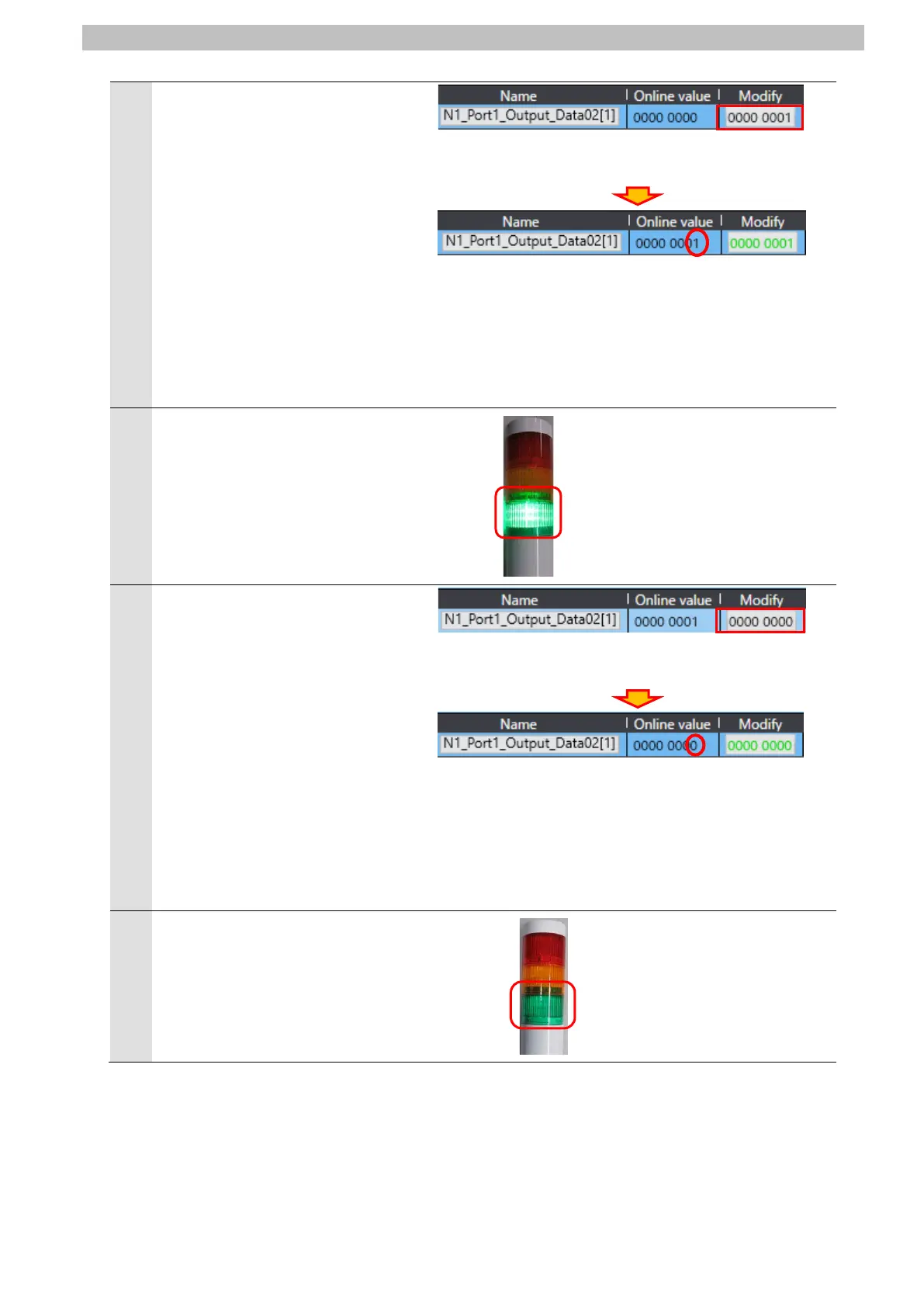
On the Watch Tab Page of Sysmac
Studio, enter 0000 0001 in the
Modify Column for
N1_Port1_Output_Data02[1] .
The bit 0 value of
N1_Port1_Output_Data02[1] (LED
unit (Green) ON/OFF) changes to 1.
*Controller turns ON the green light
of the LED unit on Signal Tower.
*Refer to 6.4. Device Variables for
details on each of the variables.
Check that the green light of the
LED unit on Signal Tower is ON.
*As shown in the figure on the right,
the green light of the LED unit on
Signal Tower is ON.
It is the same as the online value
displayed in step 21.
23
On the Watch Tab Page of Sysmac
Studio, enter 0000 0000 in the
Modify Column for
N1_Port1_Output_Data02[1].
The bit 0 value of
N1_Port1_Output_Data02[1] (LED
unit (Green) ON/OFF) changes to 0.
*Controller turns OFF the green light
of the LED unit on Signal Tower.
*Refer to 6.4. Device Variables for
details on each of the variables.
Check that Signal Tower is not lit.
*As shown in the figure on the right,
Signal Tower is not lit.
It is the same as the online value
displayed in step 23.

 Loading...


