Medium & Heavy Payload Series-Hardware Installation Manual TM12/14 Series Hardware Version: 3.2 52
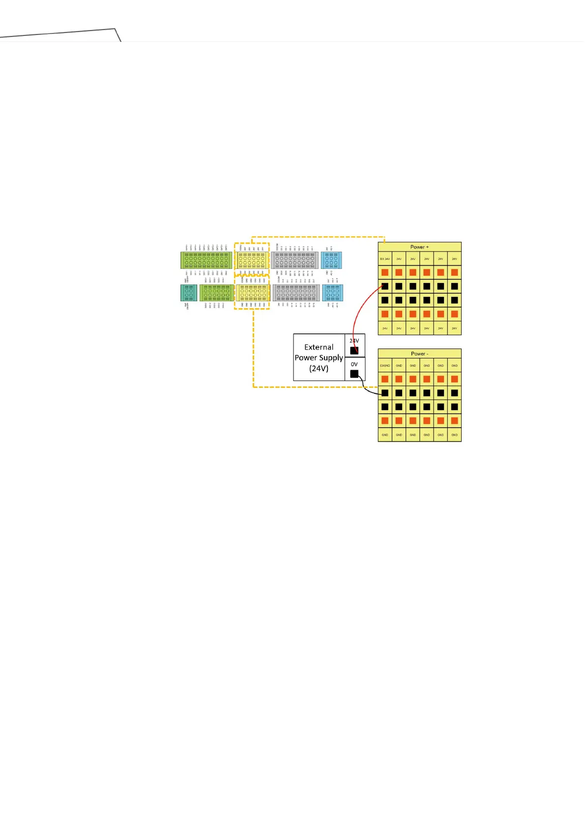
5.3.2 Power Connector
1. During boot, the control box will check for an external 24V input. If none is found, then it will switch to
the internal 24V supply.
2. The control box itself offers a 24V/2A output (24_EX). If the 24V load exceeds 2A, it enters Safe Mode
and disables the 24V output.
3. EX24V provides an external 24V input port. If the load exceeds 2A an external power supply can be
used instead. The load on EX24V must not exceed 3.5A.
Figure 44: Power Connector
5.3.3 Digital In/Out
Digital input/output each has 16 channels, and its application is connected to the following sections.
5.3.3.1 Digital Input
Inputs can be set to either sink input or source input by selection.
 Loading...