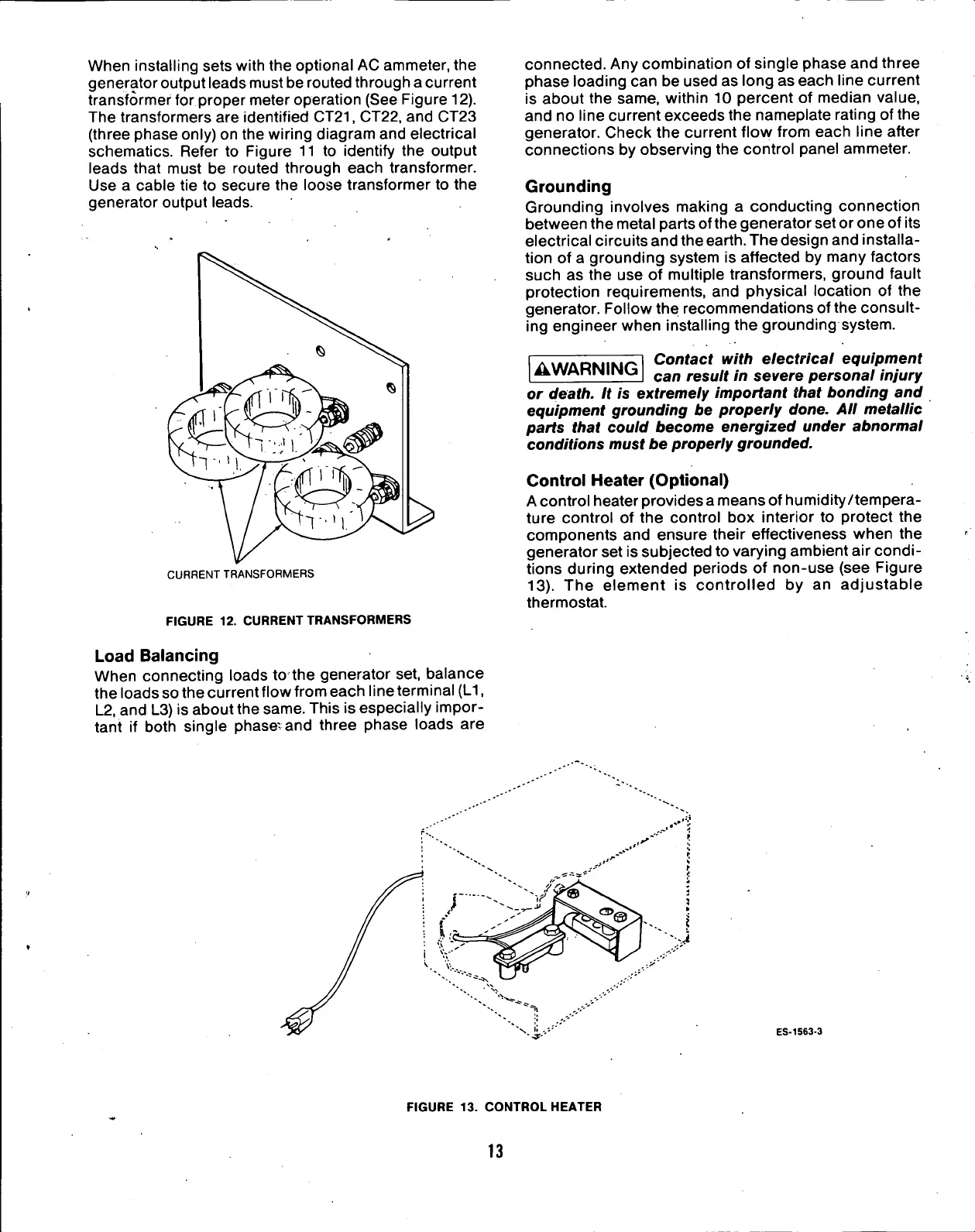
When installing sets with the optional AC ammeter, the
generator output leads must be routed through a current
transformer for proper meter operation (See Figure 12).
The transformers are identified
CT21,
CT22, and CT23
(three phase only) on the wiring diagram and electrical
schematics. Refer to Figure 11 to identify the output
leads that must be routed through each transformer.
Use a cable tie to secure the loose transformer to the
generator output leads.
CURRENT TRANSFORMERS
FIGURE 12. CURRENT TRANSFORMERS
Load
Balancing
When connecting loads to the generator set, balance
the loads so the current flow from each line terminal
(L1,
L2,
and L3) is about the same. This is especially impor-
tant if both single phase-and three phase loads are
connected.
Any combination of single phase and three
phase loading can be used as long as each line current
is about the same, within 10 percent of median value,
and no line current exceeds the nameplate rating of the
generator. Check the current flow from each line after
connections by observing the control panel ammeter.
Grounding
Grounding involves making a conducting connection
between the metal parts of the generator set or one of its
electrical circuits and the
earth.
The design and installa-
tion of a grounding system is affected by many factors
such as the use of multiple transformers, ground fault
protection requirements, and physical location of the
generator. Follow the recommendations ofthe consult-
ing engineer when installing the grounding system.
AWARNING
Confacf with electrical equipment
can result in severe personal injury
or death. It is extremely important that bonding and
equipment grounding be properly done. All metallic
parts that could become energized under abnormal
conditions must be properly grounded.
Control Heater (Optional)
A control heater provides a means of humidity/tempera-
ture control of the control box interior to protect the
components and ensure their effectiveness when the
generator set is subjected to varying ambient air condi-
tions during extended periods of non-use (see Figure
13).
The element is controlled by an adjustable
thermostat.
ES-1563-3
FIGURE 13. CONTROL HEATER
13
 Loading...