Mechanical
Connections
The generator
set
mechanical: system instaUation
includes connecting the
fuel,
exhaust, ventilation and
cooling systems. Before starting any type of
fuel
installa-
tion,
Onan recommends alii pertinent state and local
codes
be
complied with and: the installation must
be
inspected before the unit is put
in,
service.
-
FUEL
SYSTEM
Cummins engin es used on the
DF
series gen erator sets
normally use ASTM No.
2
Diesel
fuel.
They
will,
how-
ever, operate orv dcesel fuels within the speeificattons
delineated
in
the.
Cummins engine manual.
General
In
all
fuel system tnstaiFattons, cfeantrness
is ot
the
utmost importance;. Make evety effort
to
prevent en-
trance *of moisture,, dirt
or
contaminants
of
any
kind.
Clean all fuel system components before installing.
Use only compatibfe.metaf tuet lines to avofdelectroly-
sis when fuel
lines;
must be buriedL Never use gafwart.-
ized
or
copper
fuel;
tines or fittings wtth diesef fuel as
it
tends to flakeo.ff and eortfaminate the
fuel.
Useaflexibte
section
of
tubing; between, the engine and
fuel:
supply
line to withstand.vibration.
ACAUTIOt*
Never use galvanized or copper fuel
lines,,
fittings oriuettanks wit ft diesel
fuel
systems.
Condensation in the tank and lines com-
bines with the sulfur in diesel fuel to produce suffuric
acid. The molecufar structure of the copper or galvan-
ized lines
or
tanks reacts with
the,
acid and contami-
nates the fuel.
An electric solenoid shutoft vatve in the supply line
is
always desirabfe and! requtred! for indoor automatic, or
remote startmg instalfettors. Connect
the
sotenotd
'-wires
to
the battefy igpitioni ctreuit
to
open the valve
during generator set operation.
Supply
Tank
Locate the fuel tank as close as possible to the genera-
tor set and
within;
theSfoot
(1.5
metre} lift capacity ofthe
fuel pump
if
possiibfe. Choose
a
tank that has sufficient
capacity to keep thegenerator mnning. continuously at
full load for
at
least 36 hours.
AWARNING
Fuel
teaks
create
fire
and explosion
hazards
which can result
in
severe:
personal
injury or death.
Always
use
flexible
tubing
between engine andthe
fuel
supply
to avoid line failure
and
leaks
due to vibration. The
fuel
system
must
meet
applicable
codes.
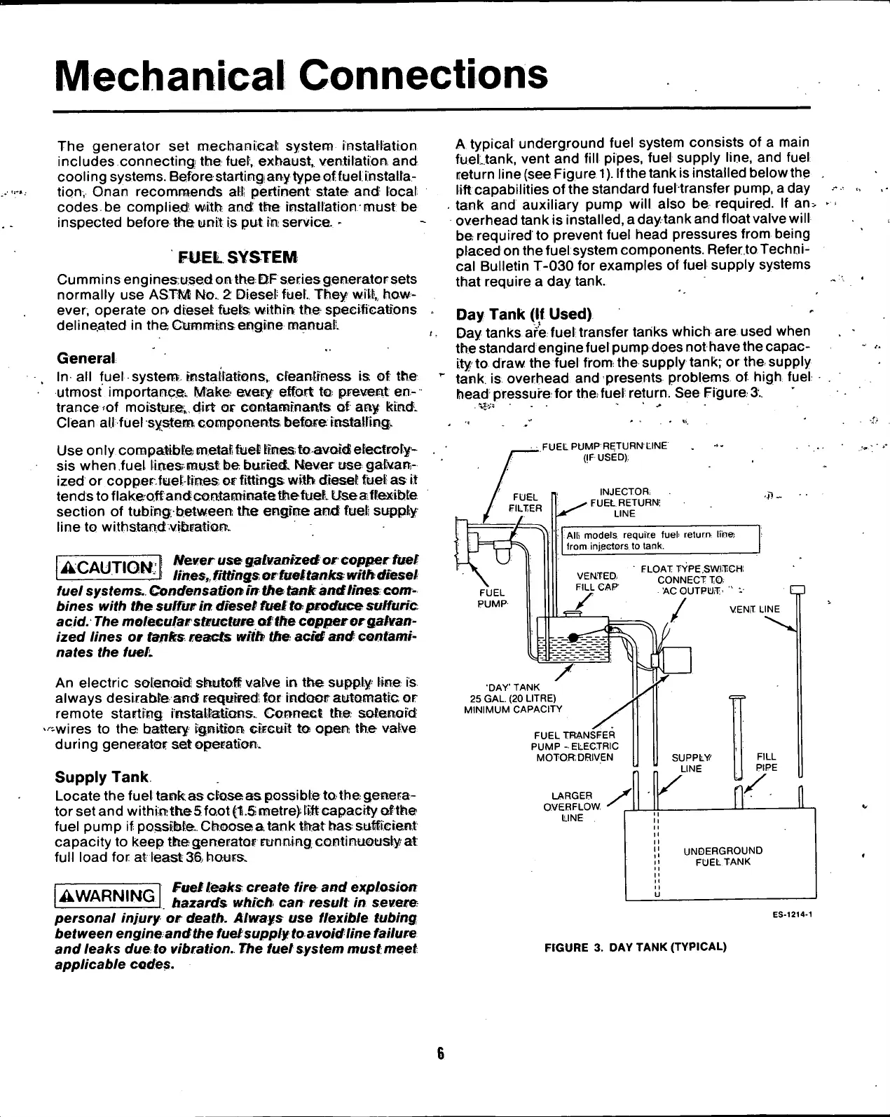
A typical underground fuel system consists
of a
main
fuel tank, vent and fill pipes, fuel supply line, and fuel
return line (see Figure
1).
Ifthe tank is installed below the
lift capabilities ofthe standard fuel transfer pump, a day
tank and auxiliary pump will also
be
required.
If
an*
overhead tank is
installed,
a day tank and float valve will
be required
to
prevent fuel head pressures from being
placed on thefuel system components. Referto Techni-
cal Bulletin T-030 for examples
of
fuel supply systems
that require
a
day tank.
Day Tank
(If
Used)
Day tanks are fuel transfer tanks which aroused when
the standard engine fuel pump does not have the capac-
ity to draw the fuel
from:
the supply tank; or the supply
tank
is
overhead and presents problems
of
high fuel
head pressure for the fuel return. See Figure
3.
FUEL PUMP RETURN LINE
(jF USED);
INJECTOR,
FUEL RETURN-
LINE
Alii models require fueh return- line!
from injectors to tank.
.fl-
FLOAT TYPE.SWITCH
CONNECT TO
AC OUTPUT
'
" V
VENT LINE
/
'DAY' TANK
25 GAL. (20 LITRE)
MINIMUM CAPACITY
FUEL TRANSFER
PUMP
-
ELECTRIC
MOTOR DRIVEN
LARGER
OVERFLOW
UNE
SUPPLY/
LINE
FILL
PIPE
ll
11
li
11
II
11
UNDERGROUND
It
11
1
•
FUEL
TANK
11
u
ES-1214-1
FIGURE
3.
DAY TANK
(TYPICAL)
 Loading...