Supply Tank Lower Than Engine: With this installation,
the day tank is installed near the generator set and
within the engine fuel pump lift capability, but below the
fuel injection system. Install an auxiliary fuel pump as
close as possible to the supply tank to pump fuel from
the supply tank to the day tank. A float switch in the day
tank controls operation of the auxiliary fuel pump.
The supply tank top must be below the day tank top to prevent
siphoning from the fuel supply tank to the day tank.
Provide a return line from the engine injection system
return connection to the day tank (near the
top).
Provide
a day tank overflow line to the supply tank in case the
float switch fails to shut off the fuel transfer pump.
AWARNING
Spilled fuel presents the hazard of
fire or explosion which can result in
severe personal injury or death. Provide an overflow
line to the
supply
tank from the day tank.
Supply Tank Higher Than Engine: Install the day tank
near the generator set and within the engine fuel pump
lift capability, but below the fuel injection system. Use
fuel line at least as large as the fuel pump inlet. The
engine fuel return line must-enter the day tank.
Include a shutoff solenoid in the fuel line between the
fuel supply tank and the day tank. It stops fuel flow when
the generator set is off.
RAIN CAP
DRIP CAP
HOLES IN END OF
INNER SLEEVE
ROOF
9 INCH MINIMUM
(230 mm).
9 INCH MINIMUM
(230 mm)
(230 mm) (230 mm)
9 INCH MIN , tt 9 INCH MIN
WALL OR PARTITION
,1)1^/-
HOLES IN
V
END
OF
INNER SLEEVE
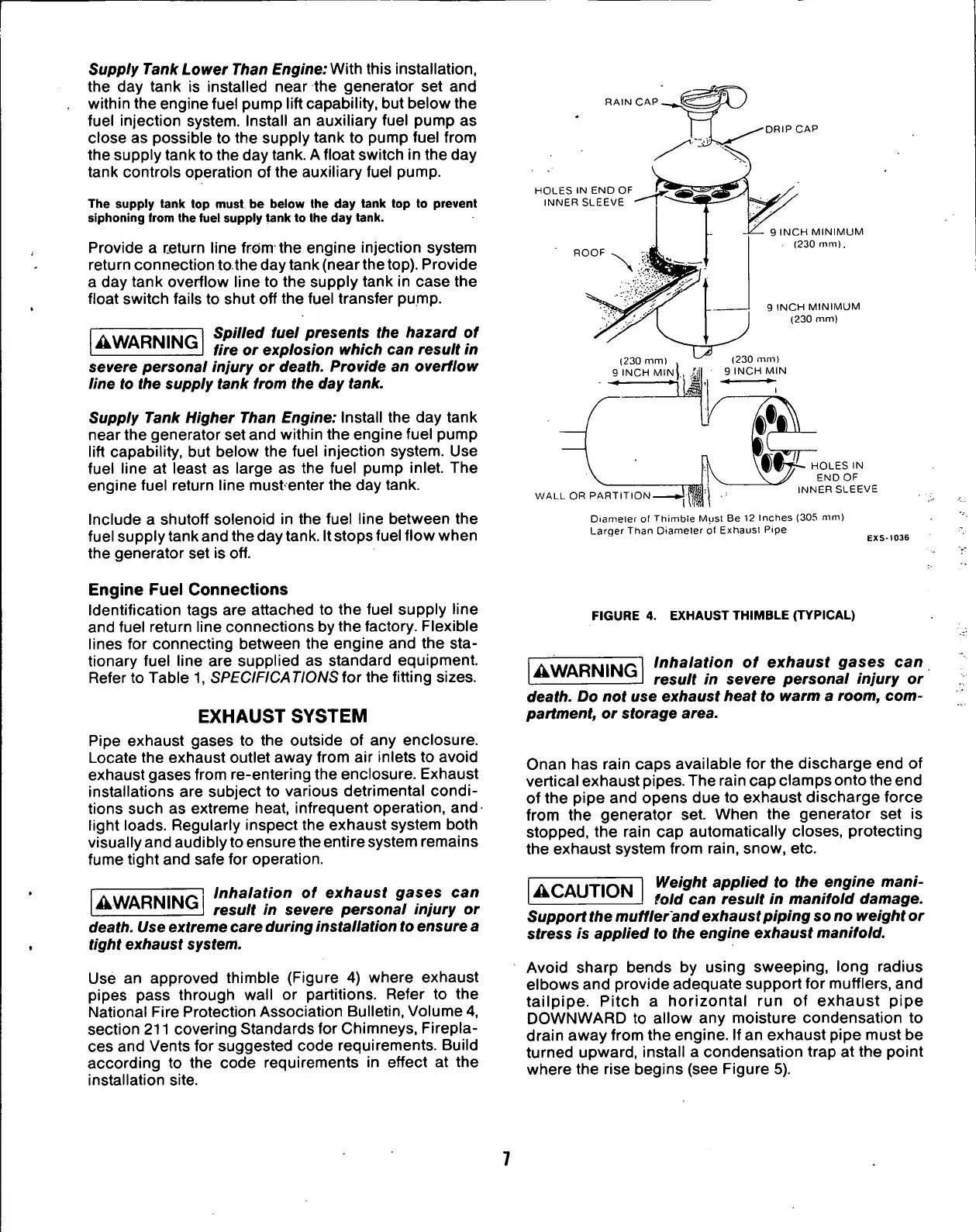
Diameter ol Thimble Must Be 12 Inches (305 mm)
Larger Than Diameter of Exhaust Pipe
EXS-1036
Engine
Fuel
Connections
Identification tags are attached to the fuel supply line
and fuel return line connections by the factory. Flexible
lines for connecting between the engine and the sta-
tionary fuel line are supplied as standard equipment.
Refer to Table 1, SPECIFICATIONS tor the fitting sizes.
EXHAUST
SYSTEM
Pipe exhaust gases to the outside of any enclosure.
Locate the exhaust outlet away from air inlets to avoid
exhaust gases from re-entering the enclosure. Exhaust
installations are subject to various detrimental condi-
tions such as extreme heat, infrequent operation, and
light loads. Regularly inspect the exhaust system both
visually and audibly to ensure the entire system remains
fume tight and safe for operation.
AWARNING
Inhalation of exhaust gases can
result in severe personal injury or
death. Use extreme care during installation
to
ensure a
tight exhaust
system.
Use an approved thimble (Figure 4) where exhaust
pipes pass through wall or partitions. Refer to the
National Fire Protection Association Bulletin, Volume 4,
section 211 covering Standards for Chimneys, Firepla-
ces and Vents for suggested code requirements. Build
according to the code requirements in effect at the
installation site.
FIGURE 4. EXHAUST THIMBLE (TYPICAL)
AWARNING
Inhalation of exhaust gases can
result in severe personal injury or
death. Do not use exhaust heat to warm a room, com-
partment, or storage area.
Onan has rain caps available for the discharge end of
vertical exhaust pipes. The rain cap clamps onto the end
of the pipe and opens due to exhaust discharge force
from the generator set. When the generator set is
stopped,
the rain cap automatically closes, protecting
the exhaust system from
rain,
snow, etc.
ACAUTION
Weight applied to the engine mani-
fold can result in manifold damage.
Support
the
mufflerand exhaust piping
so
no weight
or
stress is applied to the engine exhaust manifold.
Avoid sharp bends by using sweeping, long radius
elbows and provide adequate support for mufflers, and
tailpipe. Pitch a horizontal run of exhaust pipe
DOWNWARD to allow any moisture condensation to
drain away from the engine. If an exhaust pipe must be
turned upward, install a condensation trap at the point
where the rise begins (see Figure 5).
 Loading...