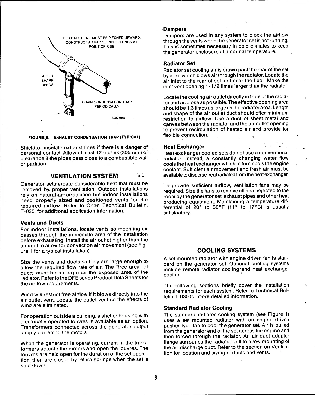
IF EXHAUST LINE MUST BE PITCHED UPWARD.
CONSTRUCT
A
TRAP OF PIPE FITTINGS AT
POINT OF RISE
AVOID
SHARP
BENDS
DRAIN CONDENSATION TRAP
PERIODICALLY
EXS-1046
FIGURE S. EXHAUST CONDENSATION TRAP (TYPICAL)
Shield.or insulate exhaust lines
if
there
is a
danger
of
personal contact. Allow
at
least
12
inches (305 mm)
of
clearance
if
the pipes pass close to
a
combustible wall
or partition.
VENTILATION
SYSTEM
Generator sets create considerable heat that must
be
removed
by
proper ventilation. Outdoor installations
rely
on
natural
air
circulation
but
indoor installations
need properly sized
and
positioned vents
for the
required airflow. Refer
to
Onan Technical Bulletin,
T-030,
for
additional application information.
Vents
and
Ducts
For indoor installations, locate vents
so
incoming
air
passes through
the
immediate area
of
the installation
before exhausting. Install the
air
outlet higher than
the
air inlet
to
allow
for
convection
air
movement (see
Fig-
ure 1
for a
typical installation).
Size
the
vents
and
ducts
so
they
are
large enough
to
allow
the
required flow rate
of air. The
"free area"
of
ducts must
be as
large
as the
exposed area
of the
radiator. Refer to the DFE series Product Data Sheets for
the airflow requirements.
Wind will restrict free airflow
if it
blows directly into the
air outlet vent. Locate
the
outlet vent
so the
effects
of
wind are eliminated.
For operation outside a building,
a
shelter housing with
electrically operated louvres
is
available
as an
option.
Transformers connected across
the
generator output
supply current
to
the motors.
When
the
generator
is
operating, current
in the
trans-
formers actuate the motors and open
the
louvres.
The
louvres are held open for the duration
of
the set opera-
tion,
then
are
closed
by
return springs when
the set is
shut down.
Dampers
Dampers
are
used
in any
system
to
block
the
airflow
through the vents when the generator set is not running.
This
is
sometimes necessary
in
cold climates
to
keep
the generator enclosure
at a
normal temperature.
Radiator Set
Radiator set cooling
air
is drawn past the rear of the set
by a fan which blows airthrough the radiator. Locate the
air inlet
to
the rear
of
set and near the floor. Make
the
inlet vent opening
1
-1
/2
times larger than the radiator.
Locate the cooling air outlet directly in front ofthe radia-
tor and as close as possible. The effective opening area
should be 1.3 times as large as the radiator
area.
Length
and shape
of
the
air
outlet duct should offer minimum
restriction
to
airflow.
Use a
duct
of
sheet metal
and
canvas between the radiator and the
air
outlet opening
to prevent recirculation
of
heated
air and
provide
for
flexible connection.
^
Heat Exchanger
*
Heat exchanger cooled sets do not use
a
conventional
radiator. Instead,
a
constantly changing water flow
cools the heat exchanger which in turn cools the engine
coolant. Sufficient
air
movement and fresh
air
must
be
available
to
disperse heat
radiated
from
the heat exchanger.
To provide sufficient airflow, ventilation fans
may be
required.
Size the fans to remove all heat rejected to the
room by the generator
set,
exhaust pipes and other heat
producing equipment. Maintaining
a
temperature
dif-
ferential
of 20° to
30°F
(11° to 17
0
C) is
usually
satisfactory.
COOLING
SYSTEMS
A
set
mounted radiator with engine driven fan
is
stan-
dard
on the
generator
set.
Optional cooling systems
include remote radiator cooling
and
heat exchanger
cooling.
The following sections briefly cover
the
installation
requirements
for
each system. Refer
to
Technical
Bul-
letin T-030
for
more detailed information.
Standard
Radiator Cooling
The standard radiator cooling system
(see
Figure
1)
uses
a set
mounted radiator with
an
engine driven
pusher type fan
to
cool the generator set.
Air is
pulled
from the generator end of the set across the engine and
then forced through
the
radiator.
An air
duct adapter
flange surrounds the radiator grill
to
allow mounting
of
the
air
discharge duct. Refer
to
the section
on
Ventila-
tion
for
location and sizing
of
ducts and vents.
 Loading...