Remote Radiator (Optional)
Remote radiators can be located a horizontal or a
verti-
cal distance, from an engine. The horizontal distance is
limited by the capability of the engine driven water pump
and the maximum external Friction Head pressure. The
vertical distance is limited to the maximum Static Head
pressure which can be imposed on coolant system
gaskets and seals without leakage of coolant from coo-
lant system components. The Friction and Static Head
pressures of each GenSet are included in their Product
Data Sheet.
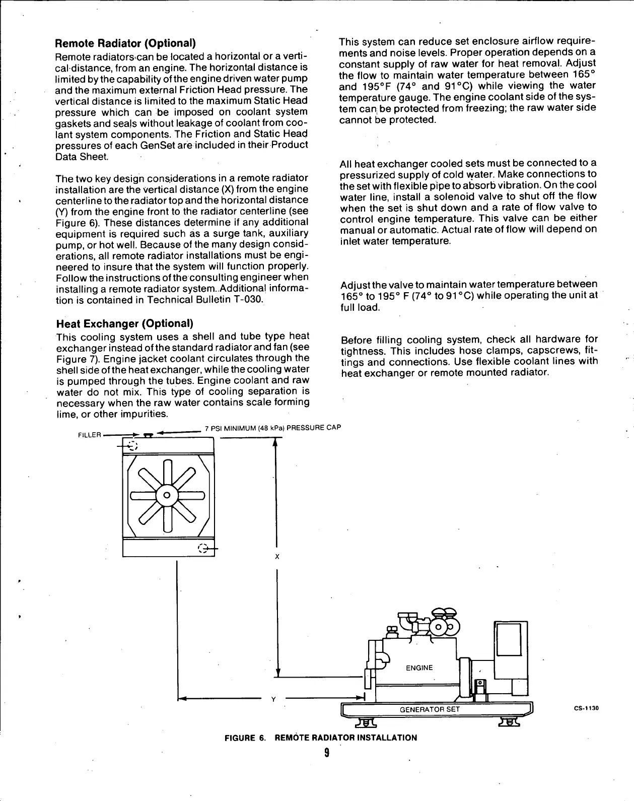
The two key design considerations in a remote radiator
installation are the vertical distance (X) from the engine
centerline to the radiator top and the horizontal distance
(Y)
from the engine front to the radiator centerline (see
Figure 6). These distances determine if any additional
equipment is required such as a surge tank, auxiliary
pump,
or hot
well.
Because of the many design consid-
erations, all remote radiator installations must be
engi-
neered to insure that the system will function properly.
Follow the instructions of the consulting engineer when
installing a remote radiator system-Additional informa-
tion is contained in Technical Bulletin T-030.
This system can reduce set enclosure airflow require-
ments and noise levels. Proper operation depends on a
constant supply of raw water for heat removal. Adjust
the flow to maintain water temperature between 165°
and 195
0
F (74° and 91
0
C) while viewing the water
temperature gauge. The engine coolant side of the sys-
tem can be protected from freezing; the raw water side
cannot be protected.
All heat exchanger cooled sets must be connected to a
pressurized supply of cold water. Make connections to
the set with flexible pipe to absorb vibration. On the cool
water line, install a solenoid valve to shut off the flow
when the set is shut down and a rate of flow valve to
control engine temperature. This valve can be either
manual or automatic. Actual rate of flow will depend on
inlet water temperature.
Adjust the valve to maintain water temperature between
165° to 195° F (74° to 91
0
C) while operating the unit at
full
load.
Heat
Exchanger
(Optional)
This cooling system uses a shell and tube type heat
exchanger instead ofthe standard radiator and fan (see
Figure 7). Engine jacket coolant circulates through the
shell side ofthe heat exchanger, while the cooling water
is pumped through the tubes. Engine coolant and raw
water do not mix. This type of cooling separation is
necessary when the raw water contains scale forming
lime,
or other impurities.
7 PSI MINIMUM (48 kPa) PRESSURE CAP
FILLER
Before filling cooling system, check all hardware for
tightness. This includes hose clamps, capscrews, fit-
tings and connections. Use flexible coolant lines with
heat exchanger or remote mounted radiator.
C
ENGINE
GENERATOR SET
m
FIGURE 6. REMOTE RADIATOR INSTALLATION
9
CS-1130
 Loading...