7-1
7. Generator
OVERVIEW
These are 4-pole, rotating-field, brushless, single-
bearing generators (Figure 7-1). Operation is as fol-
lows:
1. The engine rotates the generator field (main ro-
tor) to induce output current (AC) in the main
stator windings.
2. Generator output is proportional to the main ro-
tor (field) current supplied by the exciter rotor
through its full-wave rectifier bridge (rotating
rectifiers).
3. The genset controller (p. 5-1) rectifies and
modulates quadrature winding output (Q1, Q2)
to supply the exciter stator (F1, F2). By compar-
ing generator output voltage with a reference
value the genset control regulates field current
to maintain nominal output voltage as load var-
ies. Also, in response to transient loads, it low-
ers the voltage setpoint to allow for engine re-
covery.
4. Residual field magnetism and a permanent
magnet in one of the exciter stator poles initi-
ates “self-excitation” during startups.
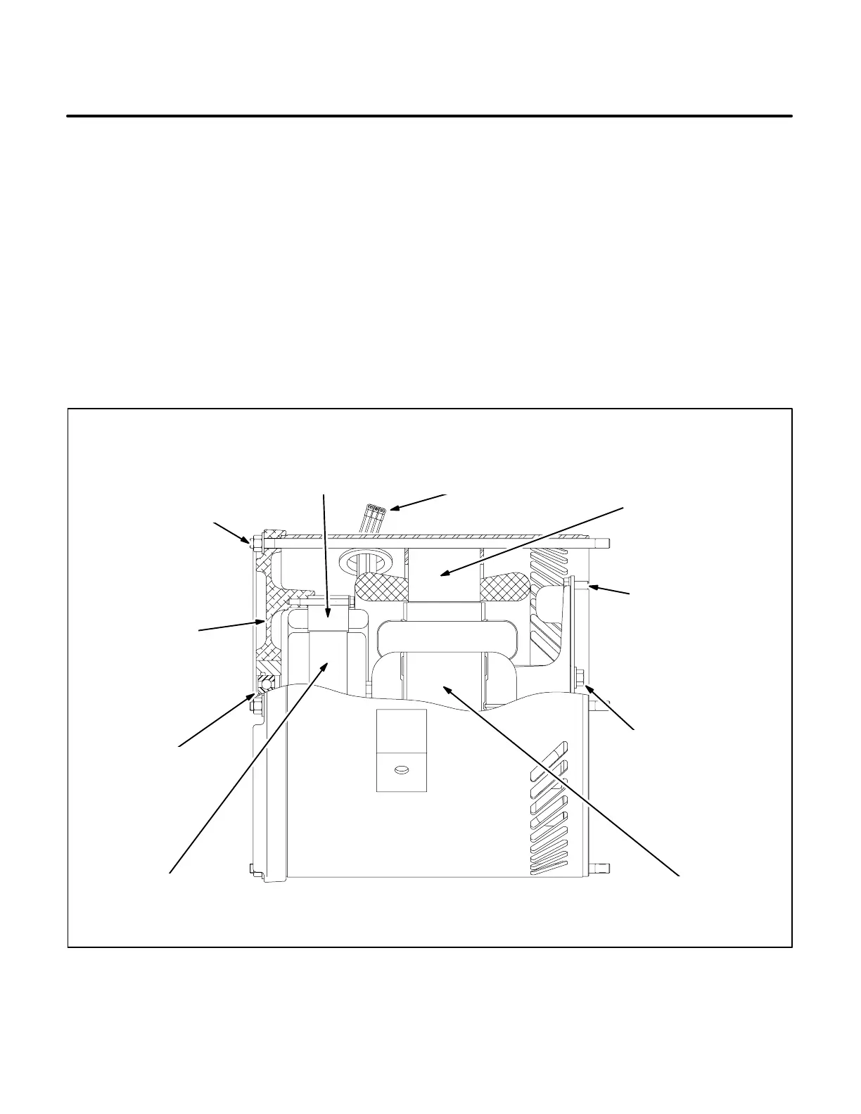
GENERATOR STATOR
(MAIN & QUADRATURE
WINDINGS)
END BELL
ASSEMBLY
ROTOR
BEARING
MAIN ROTOR
(FIELD)
DRIVE DISC BOLT (6)
TORQUE DRY TO
27−31 N-M (20−23 FT-
LB)
SMOOTH, ROUNDED
SIDES OF WASHERS
TOWARD DISC
THROUGH BOLT (4)
TORQUE DRY TO
38−43 N-M
(28−32 FT-LB)
EXCITER
ROTOR
EXCITER
STATOR
STATOR, QUADRATURE, FIELD,
& VOLTAGE SENSING LEADS
DISC HUB BOLT(6)
TORQUE DRY TO
50−57 N-M (37−42 FT-
LB) SMOOTH,
ROUNDED SIDES OF
WASHERS TOWARD
DISC
FIGURE 7-1. TYPICAL GENERATOR
Redistribution or publication of this document,
by any means, is strictly prohibited.
 Loading...

