10
REMOTE
CONTROL
R
L
R
L
R
L
IN
IN
IN
COAXIAL
OPTICAL
12
IN
IN
IN
IN
FRONT
SURR
CENTER
SUB
WOOFER
VIDEO 2
VIDEO 1
OUT
OUT
OUT
DIGITAL INPUT
VIDEO 2
VIDEO 1
DVD MONITOR
OUT
VIDEO
S VIDEO
DVD
TAPE
CD
FRONT
SPEAKERS A
FRONT
SPEAKERS B
SURROUND
SPEAKERS
CENTER
SPEAKER
L
R
L
R
AC OUTLET
ANTENNA
FM
75
AM
SUBWOOFER
PRE OUT
RL RL
AUDIO OUT
(PLAY)
AUDIO IN
(REC)
DIGITAL
OUT
OPTICAL
RL
AUDIO OUT
(PLAY)
DIGITAL
OUT
OPTICAL
S VIDEO
IN
VIDEO
IN
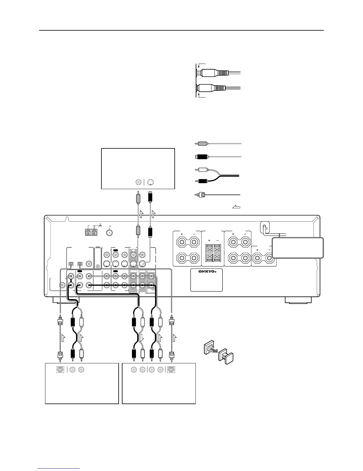
Connecting to audio/video equipment
Audio connection cable
(Analog signal)
Optical fiber cable
(Digital signal)
Audio (L)
Optical plug
Signal flow
Audio (R)
Cassette Tape deck, MD recorder,
DAT deck, CD recorder (TAPE)
CD player (CD)
TV monitor or Projector
(MONITOR OUT)
S video connection cable
(S video signal)
S video plug
Video connection cable
(Analog signal)
VIDEO
Note
The signal that comes in
from S VIDEO IN is sent
to S VIDEO OUT. The
signal that comes in from
VIDEO IN is sent to
VIDEO OUT.
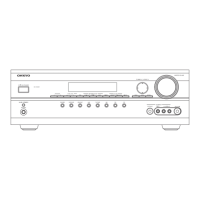
Here is explanation of how to connect the main components to the
HT-R500 in the standard manner. There are many ways that any
one component can be connected, and it is up to you to decide
which method best fits your situation. The directions given here are
only one option and should only be thought of as such. It is best to
fully understand the nature of each connector and terminal as well
as each of your components and their features to ascertain which
method of connection is best.
• Be sure to always refer to the instruction manual that came
with the component that you are connecting.
• Do not plug in the power cord until all connections have
been made.
• For input jacks, red connectors (marked R) are used for the
right channel, white connectors (marked L) are used for the
left channel, and yellow connectors (marked VIDEO) are
used for video connection.
• Insert all plugs and connectors securely. Improper connections
can result in noise, poor performance, or damage to the
equipment.
• Do not bind audio connection cables with power cords and
speaker cables. Doing so may adversely effect the sound
quality.
Improper connection
Inserted completely
About DIGITAL INPUT (OPTICAL) jack
Remove the protective caps before making connections.
When not in use, be sure to replace them.
• To connect the digital output from a component connected to
the TAPE jacks to this unit, use the OPTICAL 1 input jack.
To connect the digital output to the OPTICAL 2 or COAXIAL
input jack of this unit, it is required to change the assignment of
digital inputs to input sources by referring to “Setting the
digital inputs” on page 22.
• The TAPE OUT jack does not output the signal input from the
DIGITAL INPUT jack. (The digital signal is not converted into
analog signal.)
• To connect the digital output from CD player connected to the
CD jacks to this unit, use the OPTICAL 2 input jack.
To connect the digital output to the OPTICAL 1 or COAXIAL
input jack of this unit, it is required to change the assignment of
digital inputs to input sources by referring to “Setting the
digital inputs” on page 22.
DO NOT connect the
power cord at this
time.
 Loading...