3. Pump Start & Master Valve
This sprinkler timer allows a master valve or pump start relay to
operate whenever a station is on.
Note: If you are activating a pump from this timer, you must purchase a
Pump Start Relay.
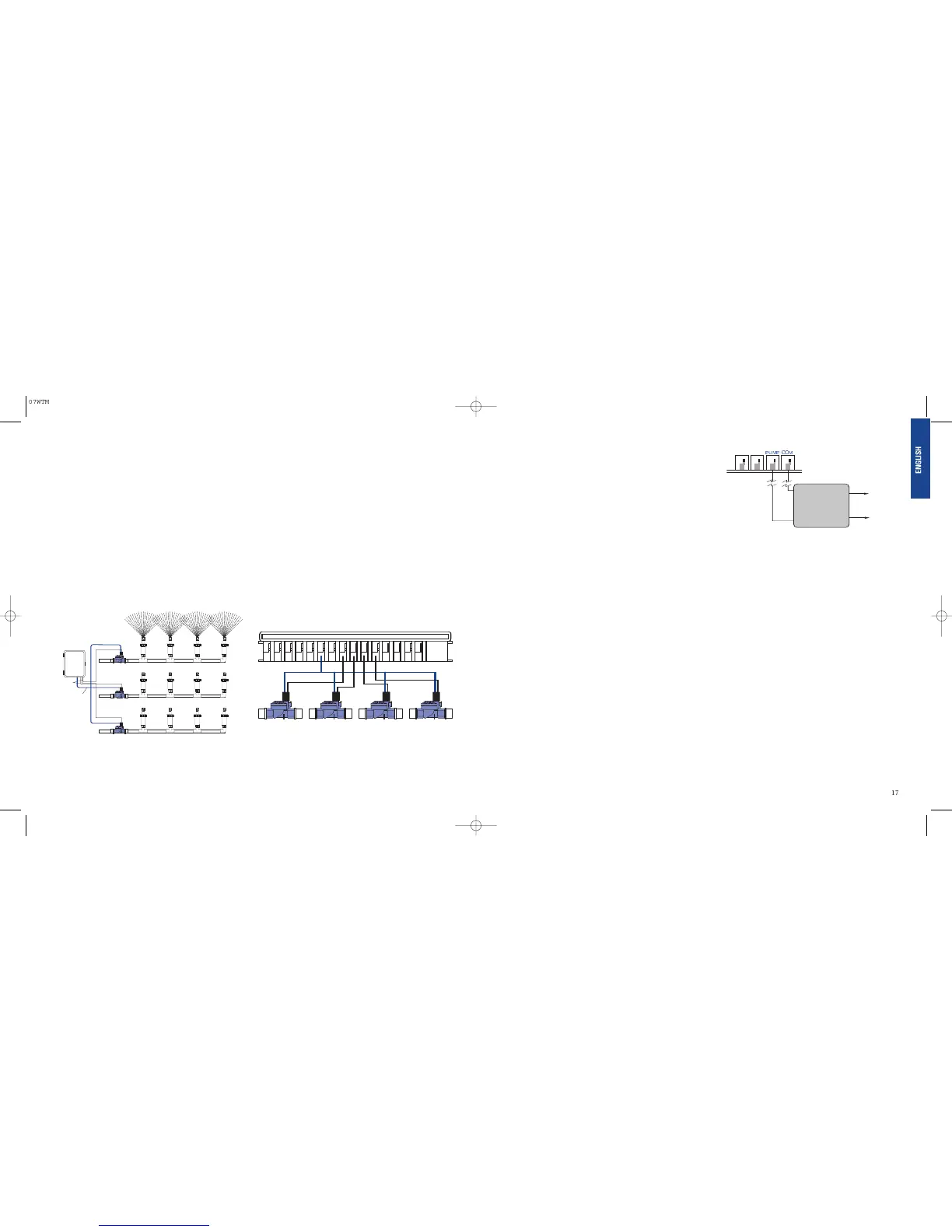
From the pump start relay (or master valve); connect one wire to the
“Pump” terminal and the other wire to the “Common” terminal. [See
Figure 28]
Section 9: Diagnostics Circuit Breaker
Smart-Scan
®
Diagnostic Fault Sensing
A diagnostic fault sensor will automatically scan for the presence of
a faulty solenoid or wiring short in a valve during each watering
sequence. If a faulty station is detected, the sprinkler timer will move
to the next working station. Smart-Scan
®
also detects faulty wiring
for the Pump or Master Control. Upon detection watering cycle is
discontinued.
Fault Notification
• Faulty Station - “FAULT STN” and station number, is displayed.
Note: When multiple faulty stations are detected, only the last
faulty station will be displayed.
• Faulty wiring for pump/master control - “
PUMP FAULT”
is displayed.
Correcting the Fault:
1. First repair the short in the wiring or replace the faulty solenoid.
2. Test the station by operating a manual watering sequence.
3. If the short is not detected after a few seconds, the fault
notification message will be terminated.
4. If the message continues, a short in the wiring still exists.
Internal Auto-Resetting Electronic Circuit
Breaker
The sprinkler timer is equipped with an internal electronic self-resetting
circuit breaker.
Possible causes of a circuit breaker tripping:
1. If lightning strikes nearby.
2. When the power supply has an electric spike.
3. If a station has a wiring short.
Whenever one of these conditions occurs, the electronic circuit
breaker may trip causing the station output from the sprinkler timer
to be halted momentarily. The batteries will continue to store the
program information and activate the LCD. After a few moments, the
sprinkler timer will automatically retest the circuit to see if the con-
dition has stopped. If so, the circuit breaker will reset itself.
16
• Taking the sprinkler wire, strip 1/2" (12 mm) of the plastic
insulation off the end of each individual wire.
• Connect one wire from each valve (it doesn’t matter which
wire) to a single “Common” sprinkler wire (usually white)
[See Figure 26]
Important: All wires should be joined together using wire nuts, solder,
and/or vinyl tape. For additional protection to waterproof connections,
an Orbit
®
grease cap can be used.
• Next connect the remaining wire from each valve to a separate
colored sprinkler wire.
• To avoid electrical hazards, only one valve should be connected
to each station.
Important: The wire can be buried in the ground; however, for more
protection wires can be pulled through PVC pipe and buried underground.
Be careful to avoid burying the wires in locations where they could be
damaged by digging or trenching in the future.
2. Connecting Valve Wires to the Sprinkler Timer
• Remove the terminal compartment cover.
• Strip 1/4" (6 mm) of the plastic insulation off the end of
each wire.
• Determine which valve you want to connect to which station.
Connect each sprinkler wire (excluding the “Common” wire)
to a separate station terminal (numbered above each blue tab)
by inserting the bare wire fully into the hole under each tab.
[See Figure 27]
• It may be necessary to open the terminal to allow for wire
insertion or removal. To do this, simply press upward on the
tab located on top of the terminal.
• Connect the common wire to the terminal (white in color)
labeled “COMMON”.
Note: Only insert one wire into each terminal. If more than two common
wires are required, splice several together so only one wire runs into each of
the two “Common” terminals. Protect the splice connection with a wire nut.
Figure 26: Connecting Sprinkler Wires to Valves
 Loading...