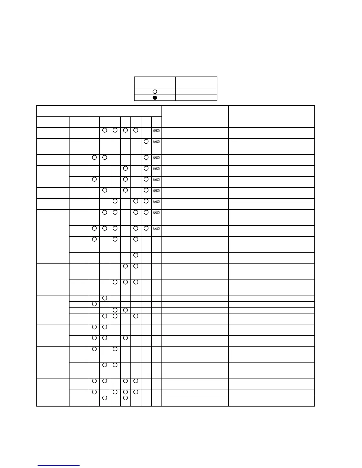
12.6. Self-diagnosis error code table
• The display screen on the wired remote control unit and the self-diagnosis LEDs (green) on the outdoor unit printed circuit board
in the outdoor unit can be used to indicate where the location of a problem is.
Refer to the table below to remove the cause of the problem, and then re-start the air conditioner system.
• If the problem disappears and operation returns to normal, the CHECK display on the remote control unit will switch off, but the
self-diagnosis LED will remain illuminated until operation is resumed.
LED Symbol Description
Off
Flashing
Illuminated
Wired remote
control unit display
Outdoor unit printed circuit board
LED
Location of problem Check location
Abnormal
display
Detail
display
2 3 4 5 6 7 8
F15 -01 Drain level Float switch problem Drain pump and drain pipe, indoor unit
connectors CN-DRMTR&CN-TH2
F16 -01 Louver switch problem Louver motor, decorative panel
connection terminal, or indoor unit louver
motor connectors
F17 -02 D. C Fan Motor problem Indoor unit D.C. Fan motor or connection
terminals
F20 -01 Indoor temperature sensor
problem
Indoor temperature sensor lead wire or
indoor unit connector or CN-TH2
-02 Remote control thermistor
problem
Remote control thermistor
F21 -01 Pipe temp. sensor problem
(indoor unit)
Pipe temperature sensor lead wire or
indoor unit connector CN-TH1
F26 -01 Remote control transmission
problem
Remote control unit cable and connection
terminals
F27 -01 Indoor/outdoor unit
disconnection problem
Indoor/outdoor unit connection cable and
connection terminals, or indoor unit and
outdoor unit power supplies (indoor side)
-05 Indoor/outdoor unit connection
error problem
Indoor/outdoor unit connection wire
(indoor side)
-01 Indoor/outdoor unit
disconnection problem
Indoor/outdoor unit connection cable and
connection terminals, or indoor unit and
outdoor unit power supplies (outdoor side)
-05 Indoor/outdoor unit connection
problem
Indoor/outdoor unit connection wire
(outdoor side)
F30 -01 System problem Total capacity for the number of indoor
units is insufficient, or over check the total
capacity and the number of indoor units
-02 Open phase, or reversed phase
of supply
Check the main power supply terminal
board connections, or switch over any two
of the power supply wires.
F31 -01 Suction pressure protection Insufficient refrigerant
-02 High-pressure cut-off Check the Refrigeration system
-06 4 way valve information Check the 4 way valve or lead wire
-10 Refrigerant system problem Insufficient refrigerant or valve operation
(closed)
F32 -05 Compressor overcurrent
protection
Open phase or lock in compressor
-06 Compressor discharge temp.
protection
Insufficient refrigerant
F40 -21 Heat exchanger outlet
temperature sensor problem
Heat exchanger outlet temperature sensor
(COND TEMP) lead wire, connector CN-
TH1
-51 Compressor discharge
temperature sensor problem
Compressor discharge temperature
sensor (DIS T. TEMP) lead wire,
connector CN-DIS
F41 -02 High pressure switch open
circuit problem
High-pressure switch lead wire, connector
CN-PSW1
-12 Low pressure sensor problem Low pressure sensor lead wire, connector
F42 -11 Current detector open circuit Outdoor unit P.C. B (NOISE FILTER) fault
or connector ACN2
94
 Loading...