Adjustment
38
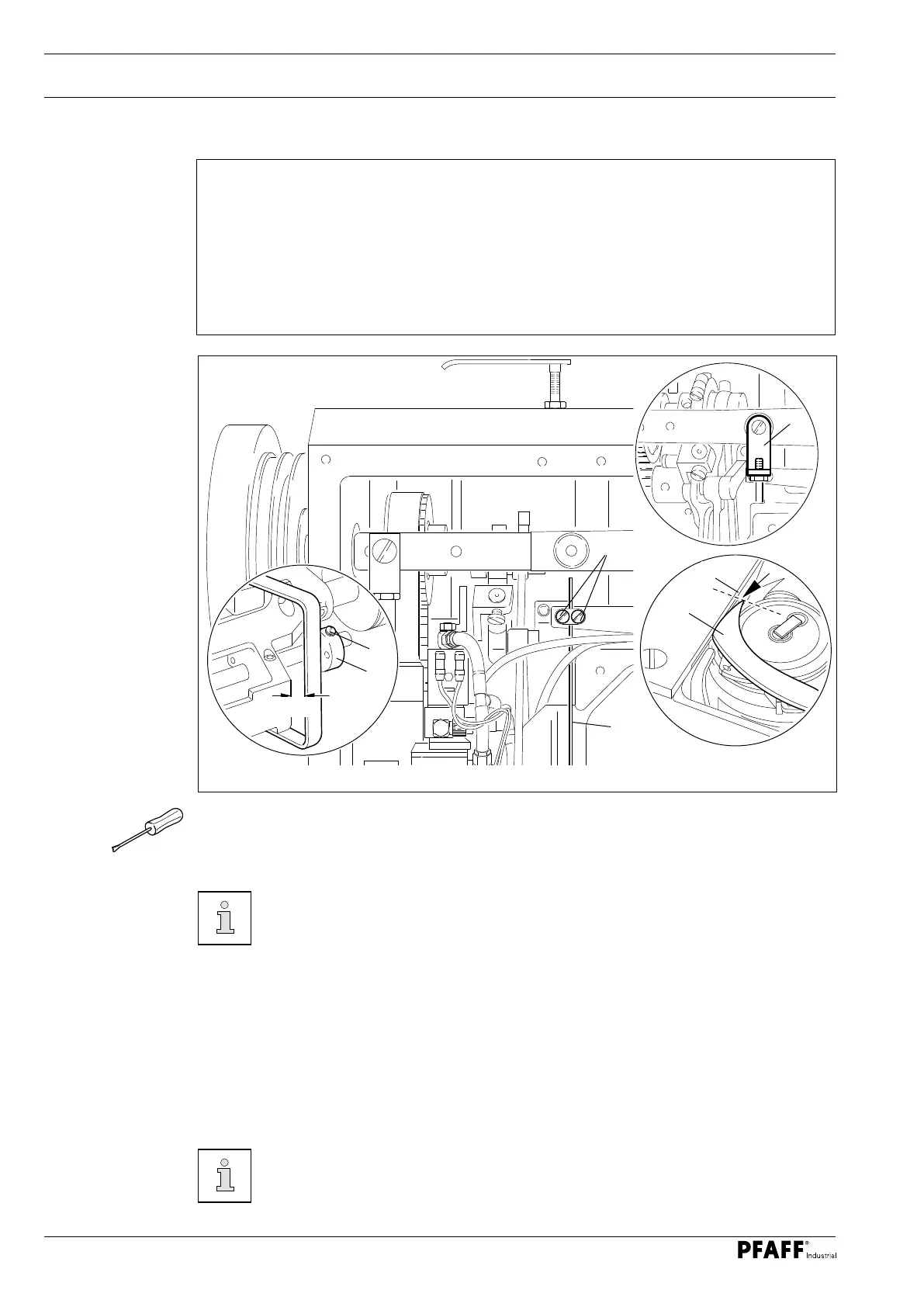
13.05.15 Tension release lever
Rule
1. There should be a clearance of approx. 7 mm between the left edge of the release
lever 8 and the housing 9 when the thread trimmer is in the neutral position and the
roller presser is raised.
2. The tension discs should be loosened far enough that the needle thread can be pulled
through easily when the tip of the thread catcher 5 is at the same level as the back
edge of the stop cam 6 of the needle plate ( see arrow) when the roller presser is fitted.
Fig. 13 - 33
O Raise the roller presser, ensuring that the thread trimmer is in the neutral position.
O Loosen the screws 1.
O Adjust the height of the actuating lever 2 ( screws 3 ) according to rule 1.
The angle bracket 4 should be unscrewed to access the screws 3 in machines
without automatic backtacking and presser foot lift ( -911/97 ).
O Move the machine to the needle rise position and activate the engaging lever by hand by
turning the handwheel.
O Lower the roller presser onto the needle plate.
O Set the tip of the thread catcher 5 to the same height as the edge of the rear stop cam 6
of the needle plate by continuing to turn the handwheel and use the retaining collar 7 to
push the release lever 8 to the left according to rule 2.
O Tighten the screws 1 in this position.
The eccentricity of the retaining collar 7 must point downwards.
2
3
4
7
1
7 mm
6
5
 Loading...