6
5
0.1 mm
2
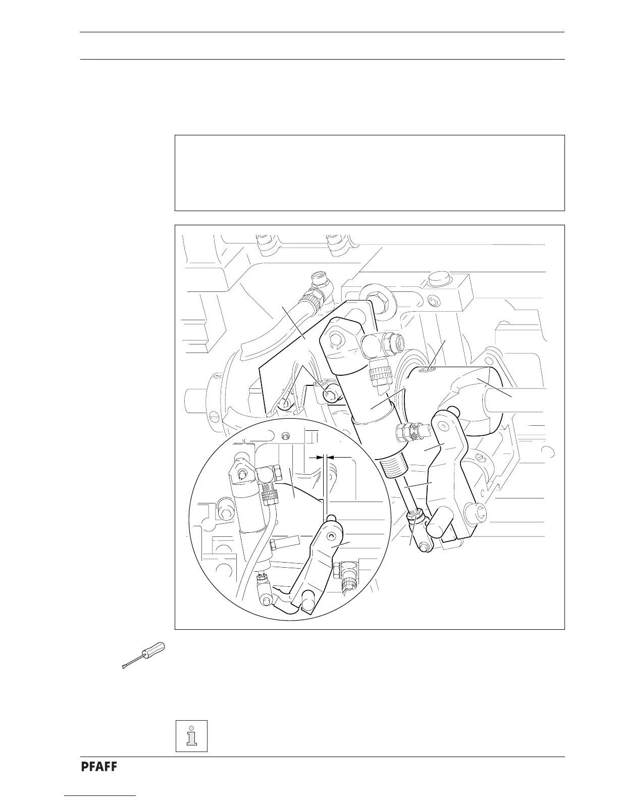
Fig. 11 - 29
6
7
3
4
1
5
8
11.06 Adjusting the thread trimmer 900/81
11.06.01 Resting position of roller lever/radial position of control cam
Requirement
1. When cylinder plunger 1 is retracted there must be a clearance of 0.1 mm between
outer edge of control cam 6 and the roller of lever 5.
2. When cylinder plunger 1 is retracted and the take-up lever is at t.d.c., control cam 6
must just move roller lever 5 to its resting position
● Fully retract plunger 1 into cylinder 2.
● Re-position cylinder mounting 3 (screws 4) according to Requirement 1.
● Push roller lever 5 into control cam 6.
● Set take-up lever at t.d.c. and turn control 6 (screws 7) according to Requirement 2.
On cylinder plunger 1, about 1 mm of thread must protrude above locknut 8.
 Loading...