AC TRACTION – DIAGNOSTICS PG DRIVES TECHNOLOGY
3 Status
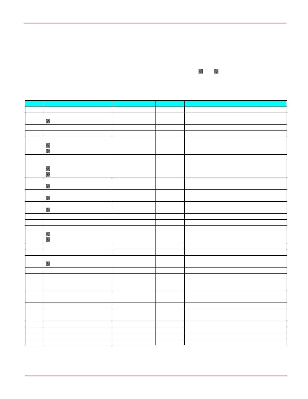
The Programmer’s Status menu shows a live-readout of parameter values. This is extremely useful when fine-tuning the system or
carrying out diagnostic work. The table below gives details of the parameters that may be viewed.
Some of the menu items have additional functions that can be accessed via the
and buttons. The options that display
recorded minimum and maximum values relate to the lifetime of the controller.
The functions, 2.10 Accelerator Slip Demand, 2.11 Damped Slip Demand and 2.12 Motor Voltage also display further status
information. This information is displayed in place of the Hz units on the screen. See Further Status Information for more details.
Ref. Parameter Programmer Text Steps/Units Notes
2.1 Drive Hours Counter Drive 0.1Hrs
2.2 Error Log
Time of Error
Fault Last recorded error code.
Measured in Drive Hours.
2.3 Battery Discharge Indicator BDI 1%
2.4 Vehicle Speed Vehicle 1Kph
2.5 Controller Temperature
Minimum Temperature
Maximum Temperature
CtrlTmp 1ºC
2.6 Steering Angle
Motor Temperature
Minimum Temperature
Maximum Temperature
StrPot
MotTemp
1%
1ºC
Units displayed as % or ºC
2.7 Battery Voltage
Maximum Voltage
BatVolts 0.1V
2.8 Capacitor (Bridge) Voltage
Maximum Voltage
Cap 0.1V
2.9 Accelerator
Auxiliary Input
Accel 1% Actual input from Accelerator.
Actual input from Auxiliary input.
2.10 Accelerator Slip Demand * DemandT 1Hz Accelerator input expressed as Slip or speed.
2.11 Damped Slip Demand * DemandR 1Hz After ramps and limits
2.12 Motor Voltage*
V displayed in bits 0 – 242.
V as % of max battery V
MotorV 0.1Vrms + = Motor V allowed
- = Motor V limited by battery V
2.13 Motor Current** Motor 10Arms
2.14 Motor (Stator) Frequency Motor 1Hz + = Forward, - = Reverse
2.15 Rotor Speed
Rotor speed in rpm
Rotor 1Hz
1rpm
+ = Forward, - = Reverse
2.16 Slip Slip 1Hz + = Drive Slip, - = Brake Slip
2.17 Maximum Slip Slip Max 1Hz Maximum permitted Slip for the current Stator
Frequency.
+ = Drive Slip, - = Brake Slip
2.18 Min V for this speed VrmsMin 0.1V Minimum permitted voltage for the current
Stator Frequency.
2.19 Actual V now VrmsNow 0.1V Voltage at current Stator Frequency.
2.20 Max V for this speed VrmsMax 0.1V Maximum permitted voltage for the current
Stator Frequency.
2.21 PGDT Use Only
2.22 PGDT Use Only
2.23 PGDT Use Only
2.24 PGDT Use Only
* See section, Further Status Information.
** The use of a current clamp or similar measuring device is recommended at lower levels.
SK79646-01 42

 Loading...