AC TRACTION – MOTOR SET-UP EXAMPLE PG DRIVES TECHNOLOGY
1.6 Brake Slip Set-up
The brake slip settings at minimum, boost and maximum should be set the same as for driving. Set the slip at the Brake Speed
Base Point so that the brake slip graph is linear from the Boost to the Maximum point.
Therefore, in this example the settings would be as follows:
• Direction and Neutral Braking Slip Minimum: 1.57Hz
• Direction and Neutral Braking Slip Boost: 2.24Hz
• Braking Slip Base: 2.24Hz
• Braking Slip Maximum: 2.24Hz
1.7 Brake Voltage Set-up
For braking there are separate voltage level settings for Neutral and Direction Braking at the Minimum and Boost Speed points.
This is designed to soften the end of braking in neutral. The Footbrake uses the same motor set-up as Direction Braking. The
Direction Braking voltage levels at Minimum and Boost level should be set at 50% of the drive voltage levels. For Neutral Braking
the Minimum and Boost Voltage levels should also be set to 50% of the drive voltage levels. At Base and Maximum the voltage
levels are set the same as for driving.
Therefore, in this example the settings would be as follows.
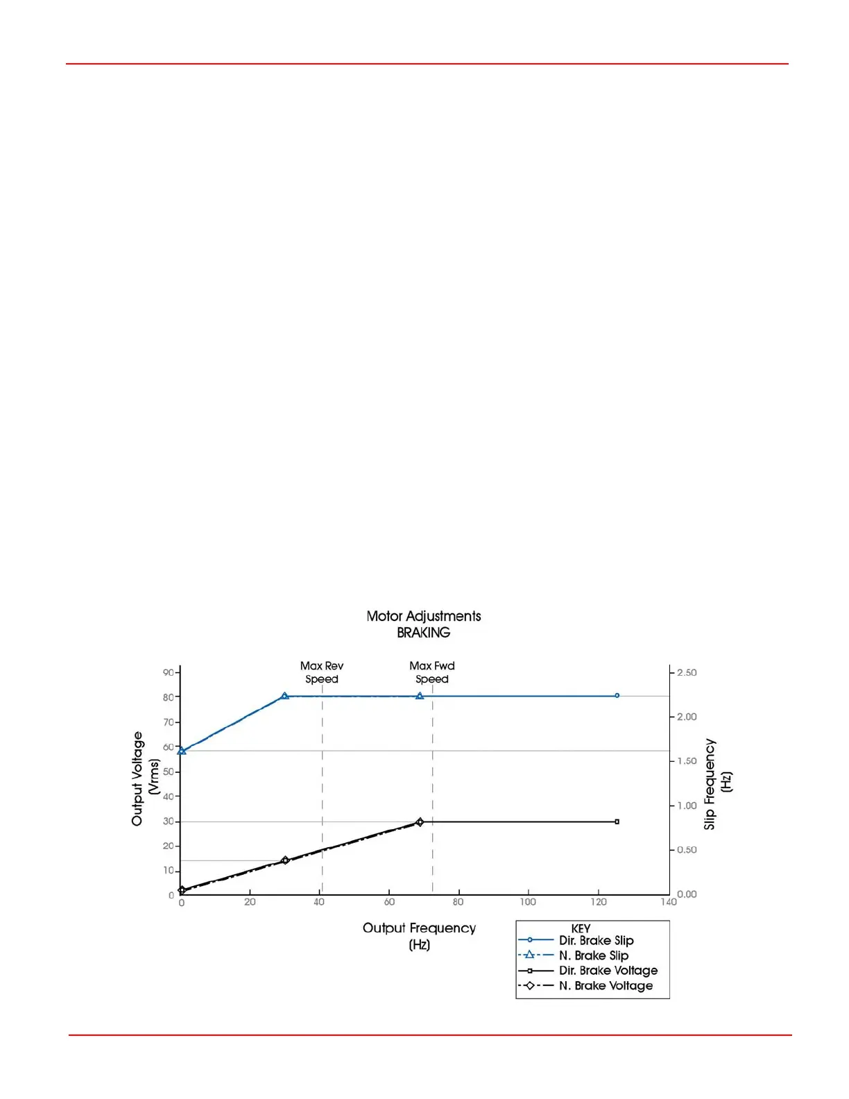
• Direction Braking Voltage Minimum: 1.7Vrms
• Direction Braking Voltage Boost: 15Vrms
• Neutral Braking Voltage Minimum: 1.7Vrms
• Neutral Braking Voltage Boost: 15Vrms
• Braking Voltage Base: 30Vrms
• Braking Voltage Maximum: 30Vrms
By combining the braking values calculated so far, the following graph can be plotted.
SK79646-01 70

 Loading...