PG DRIVES TECHNOLOGY AC TRACTION – HAND-HELD PROGRAMMER
4 Programmer Map
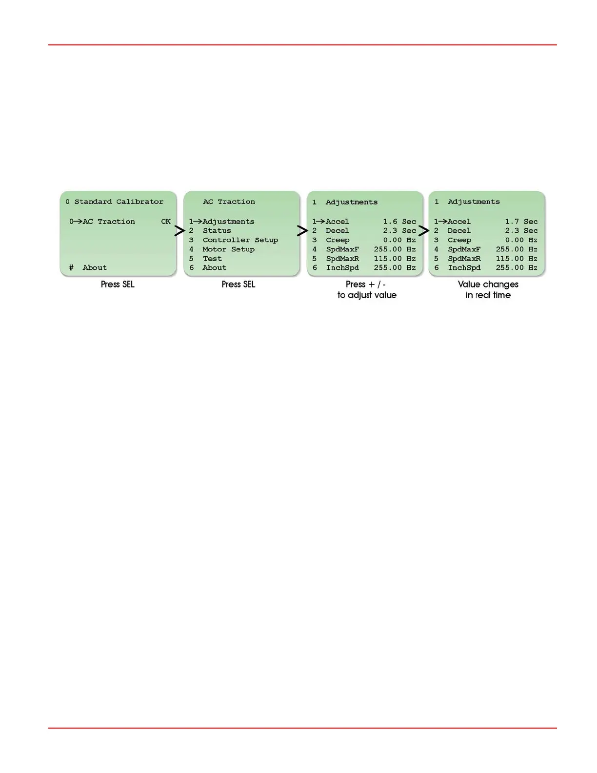
The Programmer has a menu structure that allows smooth and swift parameter adjustments, as well as system diagnostics and
testing.
Upon initialization, the Programmer will display the ‘Calibrator’ screen, as shown below, which prompts you to select the controller
type. (AC Traction is shown in this example). Once the controller type is selected, there are then programming, diagnostic and
test options available.
Some parameters e.g. 3.8 Truck Type Select, require that the power to the controller be cycled via the keyswitch before the new
value will be accepted. These parameters are marked on the Programmer’s screen with the word ‘Key’.
4.1 Programming, Diagnostic and Test Options
4.1.1 Adjustments
This menu includes parameters related to the application’s performance, such as acceleration, speeds and BDI calibration. Refer
to the Adjustments chapter for full details.
4.1.2 Status
This menu allows you to select system and controller information for display, such as vehicle speed, battery voltage and controller
temperature. Refer to the Diagnostics chapter for full details.
4.1.3 Controller Set-up
This menu includes parameters related to the controller’s operation, such as I/O configuration, throttle response and CAN node
set-up. Refer to the Controller Set-up chapter for full details.
4.1.4 Motor Set-up
This menu includes parameters specifically related to the type of motor being used. Refer to the Motor Set-up chapter for full
details.
4.1.5 Test
This menu allows you to select controller I/O status for display, such as the state of digital and analogue inputs, or contactor and
LED outputs. Refer to the Diagnostics chapter for full details.
SK79646-01
9

 Loading...