PG DRIVES TECHNOLOGY AC TRACTION – MOTOR SET-UP EXAMPLE
• Drive Slip Minimum: 1.57Hz
• Drive Slip Boost: 2.24Hz
• Drive Slip Base: 2.24Hz
• Drive Slip Maximum: 2.24Hz
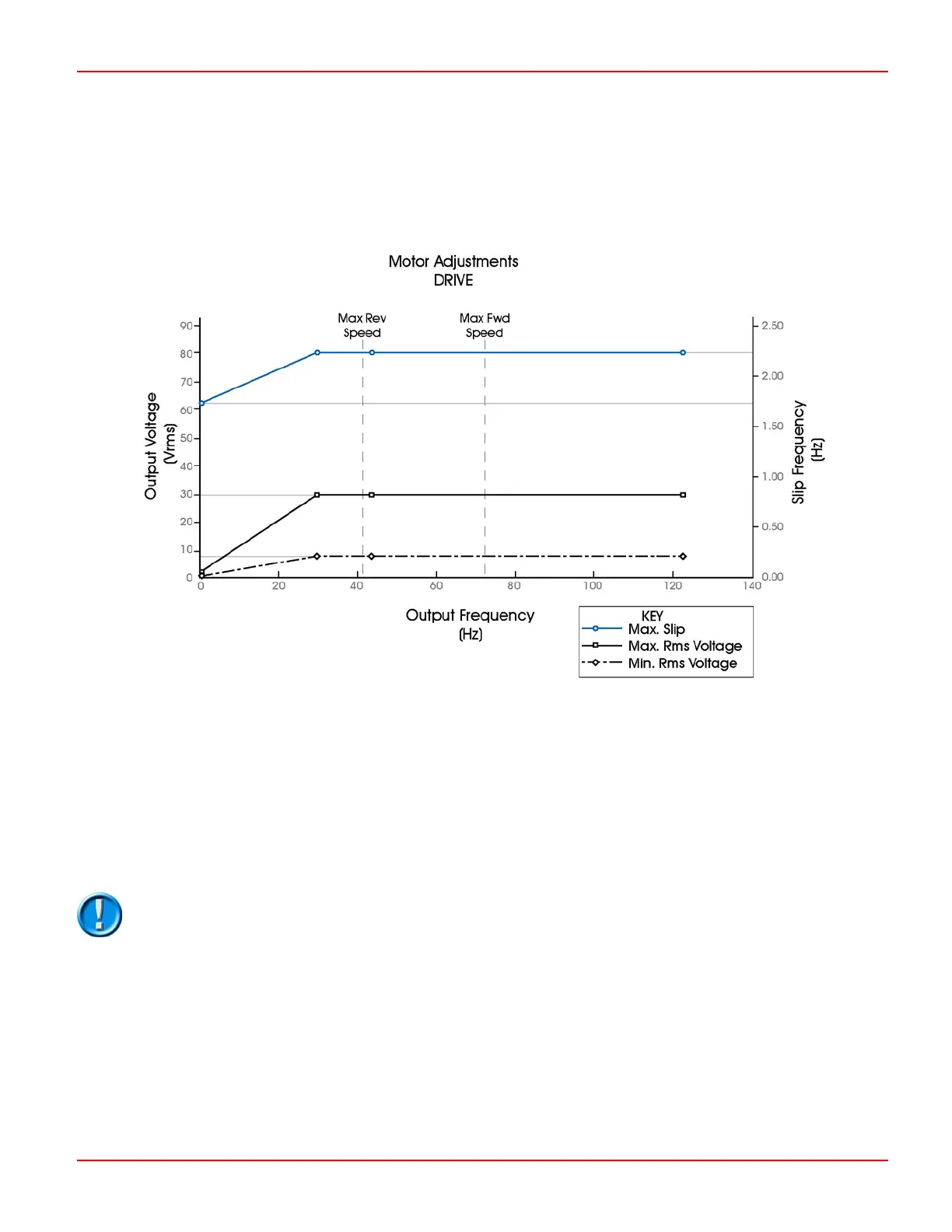
By combining the values calculated so far, the following graph can be plotted.
The ‘basic’ motor set-up for drive is now defined. Depending on the feedback from the speed encoder and the torque demand
from the accelerator, the controller will vary the voltage between the minimum and maximum values shown on the graph. The
slip will vary between 0Hz and the maximum setting for the given speed.
1.4 Motor set-up – Braking
The voltage and slip settings for braking are basically lower than those for driving. To ensure a smooth braking performance, a
separate base speed point is added for braking. This allows the set up of a linear voltage line over the full speed range. Three
different braking torque levels can be set in the Adjustments menu, 1.9 Direction Regen Braking, 1.10 Neutral Regen Braking and
1.11 Footbrake Regen Braking.
Normally, the Direction Braking has the highest torque level, therefore, 1.9 Direction Regen Braking
must be set to 100% in the Adjustments menu before starting to set up the motor braking table.
1.5 Defining the Braking Motor Speed Base Point
The parameter 4.30 Braking Motor Speed Base is normally set to about 1½ times the value of the drive base speed.
Therefore, in this example the setting would be as follows.
• Braking Motor Speed Base: 66Hz
SK79646-01 69

 Loading...