TROUBLESHOOTING AND ELECTRICAL SYSTEM: FE400 ENGINE Electrical Circuits
2003 Pioneer 1200/1200SE Gasoline Vehicle Maintenance and Service Manual Page 11-9
11
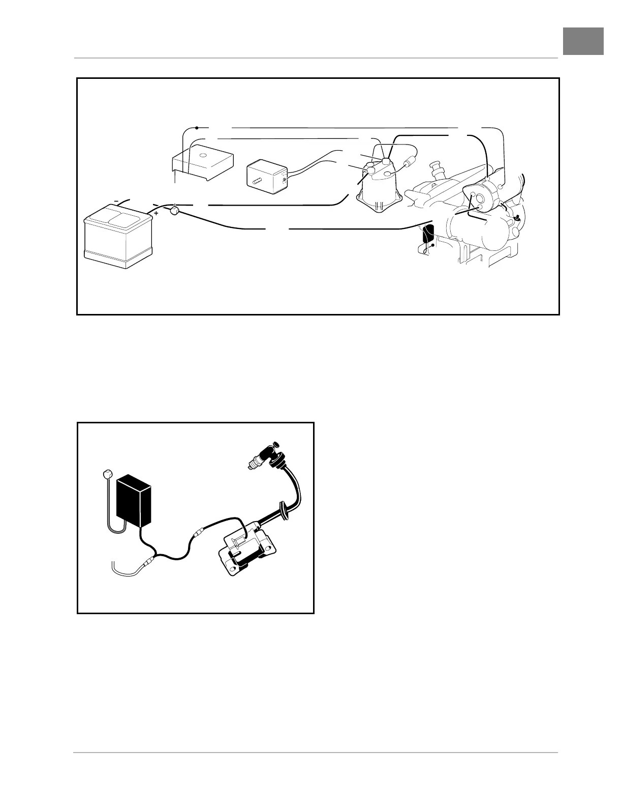
ENGINE IGNITION CIRCUIT
The engine ignition circuit is independent of all other circuits except the kill circuit. It consists of the ignition coil
with internal igniter, spark plug, RPM limiter, and connecting wires (Figure 11-6, Page 11-9).
ENGINE KILL CIRCUIT
The ignition coil supplies electrical power to the spark plug; therefore, the proper way to stop the engine is to
run this electrical power to ground, bypassing the spark plug (Figure 11-7, Page 11-10).
The engine kill circuit consists of the key switch and connecting wires. The engine can be stopped by turning
the key switch to the OFF position. See Lockout Cam Circuit on page 11-11.
Figure 11-5 Key-Start Generator Circuit
Figure 11-6 Ignition Circuit
F2
DF
F1
A2
A1
FRAME
GROUND
BATTERY
VOLTAGE
REGULATOR
STARTER /
GENERATOR
ENGINE
G
R
E
E
N
SOLENOID
RED
RED
RED
RED
WHITE
RED
RED
WHITE
YELLOW
YELLOW
BLACK
BLACK
BLACK
BLACK
DIODE
DIODE
GROUND
RPM LIMITER
IGNITION COIL
WITH IGNITER
SPARK PLUG
ENGINE KILL
WIRE
BULLET
CONNECTOR