STEERING AND FRONT SUSPENSION Rack and Pinion
Page 7-6 2003 Pioneer 1200/1200SE Gasoline Vehicle Maintenance and Service Manual
7
Rack and Pinion Removal, Continued:
3. Remove the lug nuts from the front wheels.
4. Remove the cotter pins (18) and ball joint retaining nuts (24) (Figure 7-20, Page 7-11).
5. Remove the ball joints (23) from the spindle assemblies.
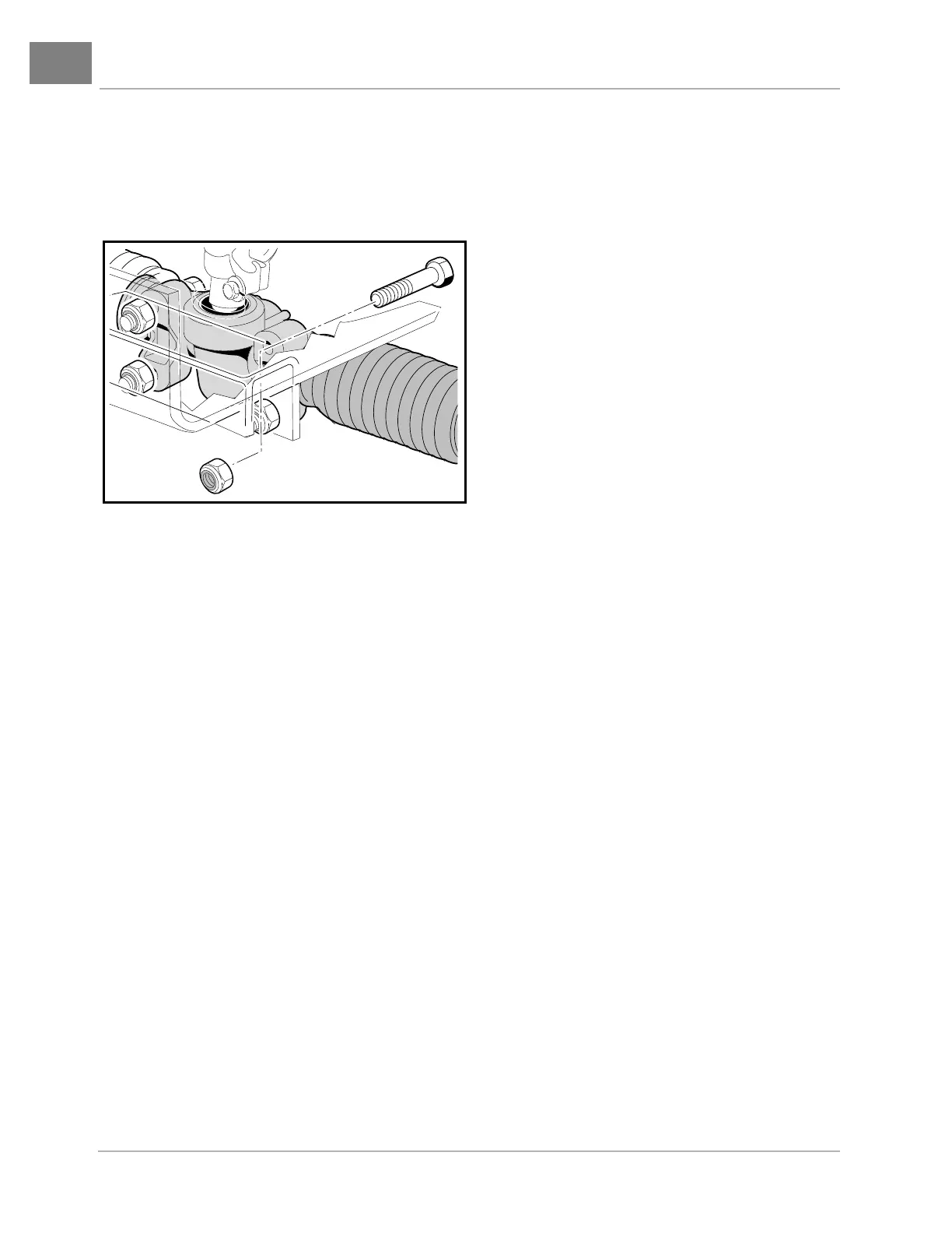
6. Remove the four bolts (20), washers (21) and nuts (22) from the steering rack and pinion assembly
mounting bracket (Figure 7-20, Page 7-11). Also see Figure 7-7, Page 7-6.
7. Remove the bolt (27) and lock washer (Figure 7-3, Page 7-2) from the universal joint, then remove the
rack and pinion assembly and universal joint from the vehicle (Figure 7-8, Page 7-7).
RACK AND PINION DISASSEMBLY
1. Remove the two ball joints and inspect for excessive wear (Figure 7-9, Page 7-7).
2. Remove both drag links (19) (Figure 7-10, Page 7-7).
3. Remove both bellows clamps (metal clamps or plastic wire ties) (Figure 7-11, Page 7-8).
NOTE: If the dust seal bellows are secured with a metal clamp, remove the clamp. Do not reuse the clamp
when the rack and pinion is reassembled. Use a plastic wire tie to secure the dust seal bellows.
4. Remove the two hex nuts (12) and slide off both of the dust seal bellows (10) (Figure 7-20, Page 7-11).
5. Remove rack screw nut (8), rack guide screw (7), rack guide pressure spring (6) and the rack guide (5).
6. Remove the universal joint assembly from the pinion (3) by removing the bolt and then sliding off the uni-
versal joint.
7. Remove the dust seal (Figure 7-14, Page 7-8).
8. Remove the snap ring (Figure 7-15, Page 7-8).
9. Install the universal joint onto the pinion and place a fork or a large open-end wrench under the universal
joint (Figure 7-16, Page 7-9). Gently pry the pinion from the housing (Figure 7-17, Page 7-9).
10. Remove the U-joint from the pinion (3) (Figure 7-20, Page 7-11).
11. If the ball bearing (15) (Figure 7-20, Page 7-11) has been damaged, remove the c-type stop ring (16)
(Figure 7-15, Page 7-8) and press the bearing off (Figure 7-13, Page 7-8).
Figure 7-7 Rack and Pinion Bolts
 Loading...