ALIGNING THE FM
MPX SECTION
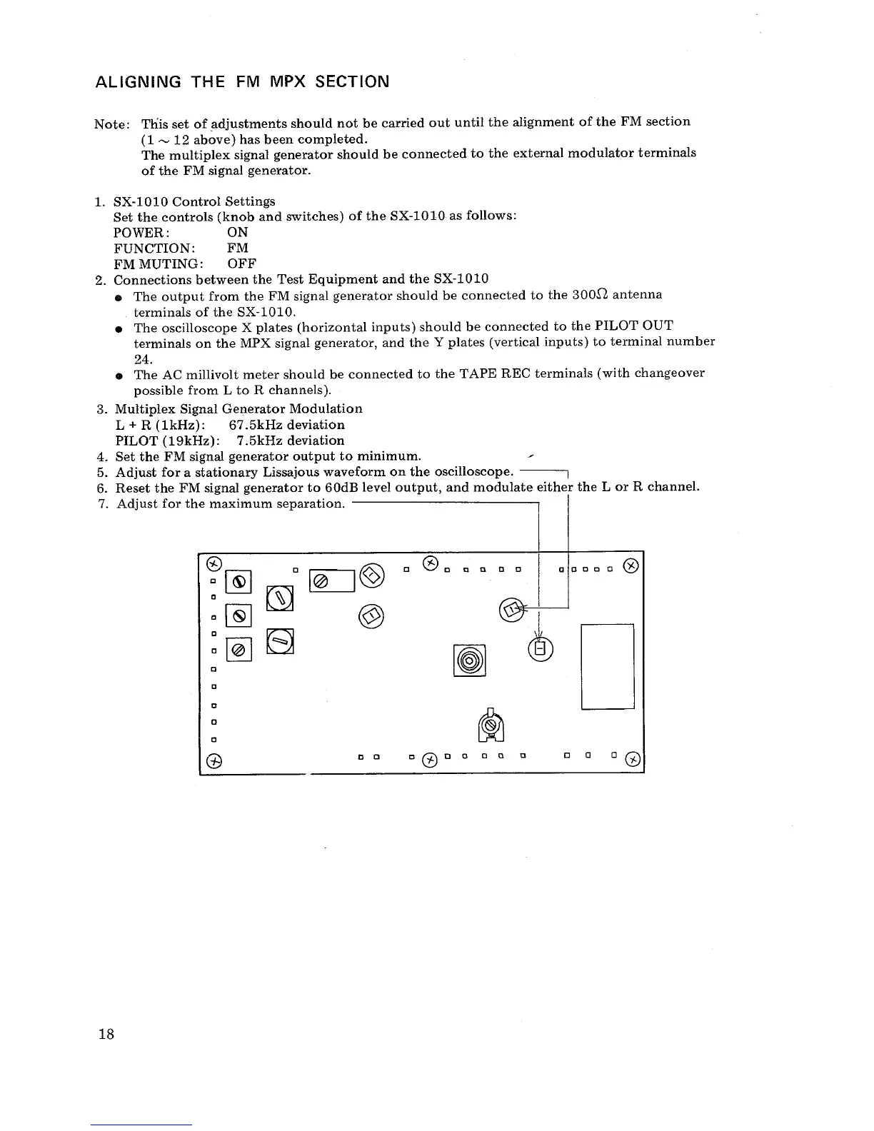
Note: This
set of adjustments should not be carried out until the alignment of the FM section
(1 ~ 12 above) has been completed.
The multiplex signal generator should be connected to the external
modulator terminals
of the FM signal generator.
1. SX-
1010 Control Settings
Set the controls (knob and switches) of the SX-
1010 as follows:
POWER:
FUNCTION: FM
FM MUTING:
OFF
2. Connections between the Test Equipment and the SX-
1010
. The output
from the FM signal generator should be connected to the
300,Q antenna
terminals of the SX-
1010.
. The oscilloscope X plates (horizontal inputs) should be connected to the PILOT OUT
terminals on the MPX signal generator
, and the Y plates (vertical inputs) to terminal number
24.
. The AC
millivolt meter should be connected to the TAPE REC
terminals (with changeover
possible from L to R channels).
3. Multiplex Signal Generator Modulation
L + R (1kHz): 67.
5kHz deviation
PILOT (19kHz): 7.5kHz deviation
4. Set the FM signal generator output to minimum.
5. Adjust for a stationary Lissajous
waveform on the oscilloscope.
6. Reset the FM signal generator to 60dB level output
, and modulate either the L or R channel.
7. Adjust for the maximum separation.
:~
:~ 8
aocco 0
~ D
a a
 Loading...