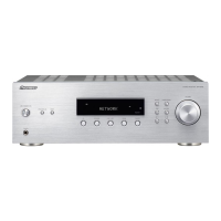
SX-
1 01 0
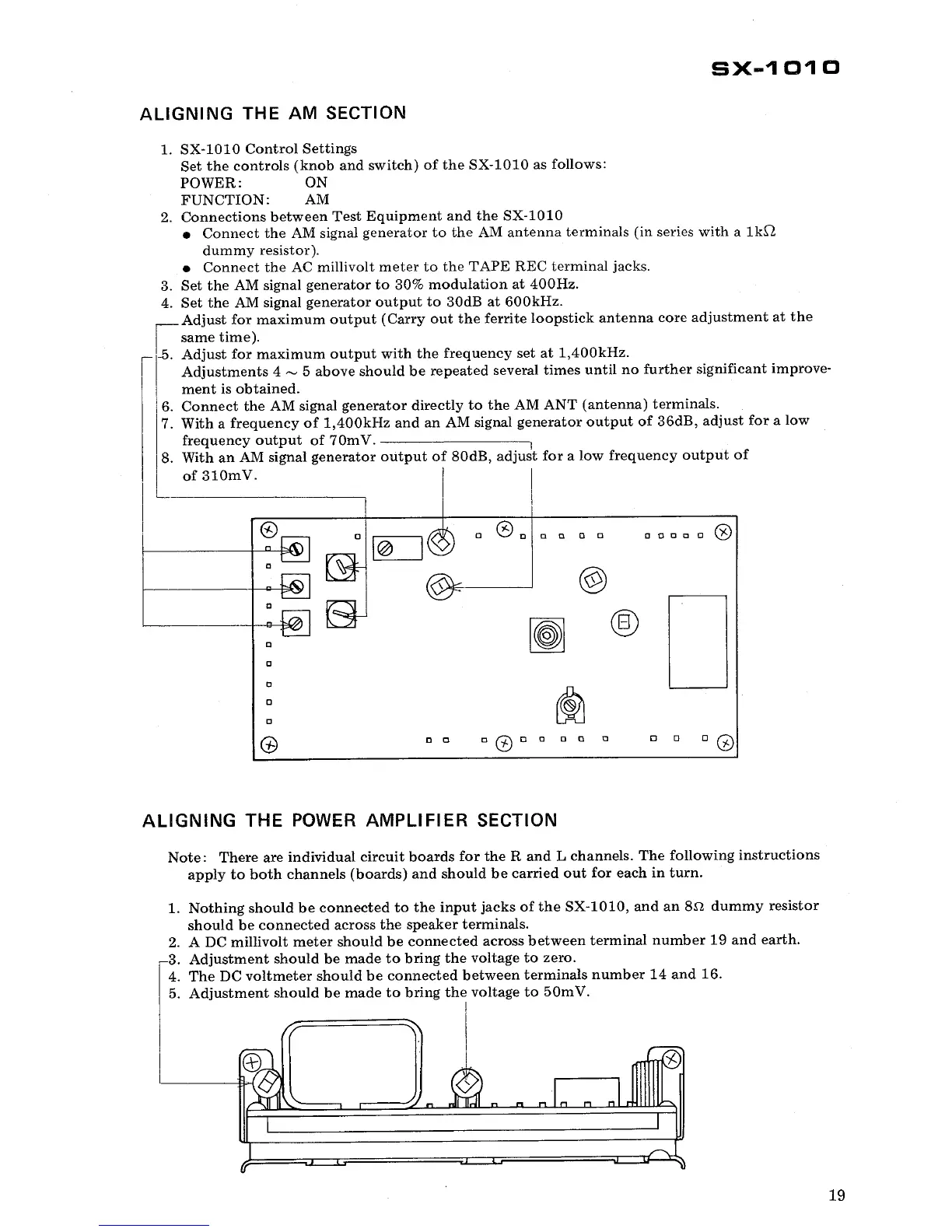
ALIGNING THE AM SECTION
1. SX-
1010 Control Settings
Set the controls (knob and switch) of the SX-
1010 as follows:
POWER:
FUNCTION: AM
2. Connections between Test Equipment and the SX-
1010
. Connect
the AM signal generator to the AM antenna terminals (in series with a
1k,Q
dummy resistor).
. Connect the AC millivolt meter to the TAPE REC terminal jacks.
3. Set the AM signal generator to
30% modulation at 400Hz.
4. Set the AM signal
generator output to 30dB at 600kHz.
Adjust for maximum output (Carry out the ferrite loopstick antenna core adjustment at the
same time).
-5. Adjust for maximum output with the frequency set at 1
400kHz.
Adjustments 4 ~ 5 above should be repeated several times until no further significant
improve-
ment is obtained.
. Connect the AM signal
generator directly to the AM ANT (antenna) terminals.
7. With a frequency of 1
400kHz and an AM signal generator output
of 36dB
, adjust for a low
frequency output of 70mV.
8. With an AM signal generator output of 80dB
, adjust for a low frequency output of
of 310mV.
",,"c" ~
(0)
" a
" CD a
" "
a 0
ALIGNING THE POWER AMPLIFIER
SECTION
Note: There are individual circuit boards for the Rand L channels. The following instructions
apply to both channels (boards) and should be carried out for each in turn.
1. Nothing should be connected to the input jacks of the SX-
101O, and an 8.\1 dummy resistor
should be connected across the speaker terminals.
2. A DC millivolt meter should be connected across between terminal number 19 and earth.
3. Adjustment should be made to bring the voltage to zero.
4. The DC voltmeter should be connected between terminals number 14 and 16.
5. Adjustment should be made to bring the voltage to 50m
 Loading...