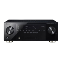
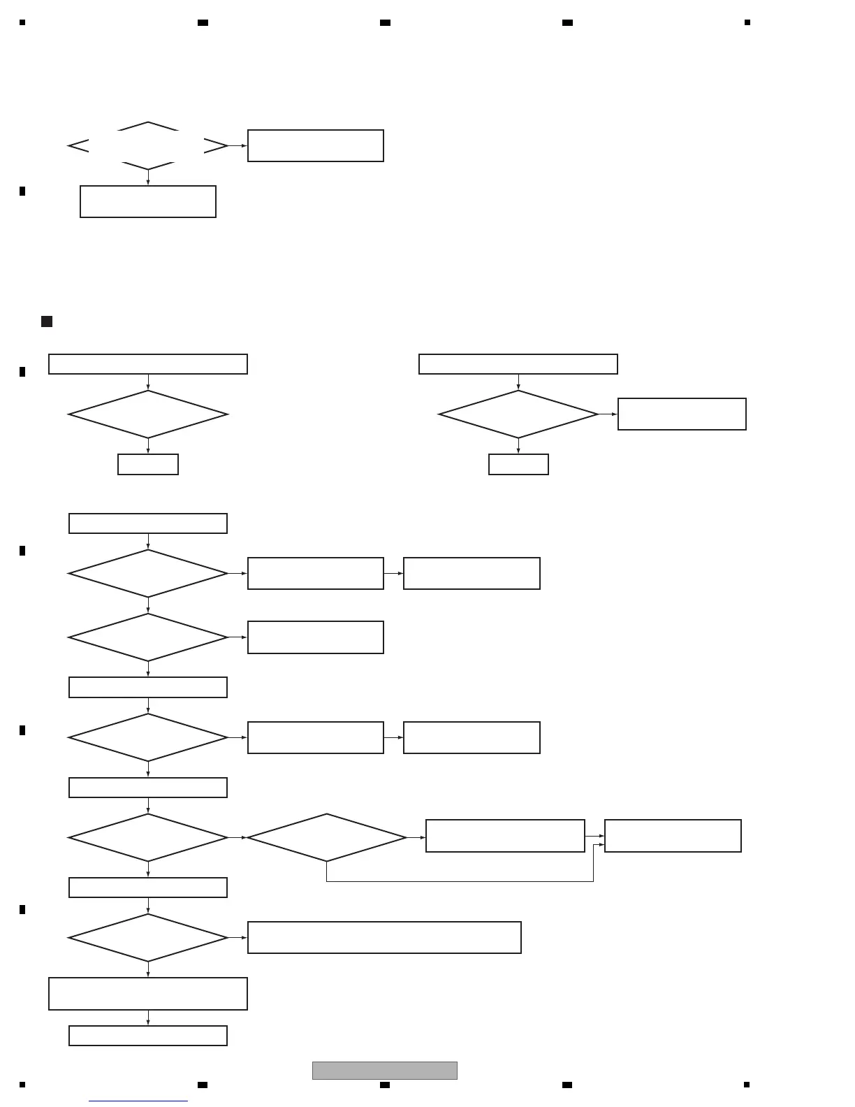
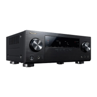
5. DIAGNOSIS
Step 0: Preliminary confirmation
CP1306,CN1304,CP1305,CP1304,CN1303
To Step 1
Are the connectors
securely inserted?
Step 1: Fixed board
Confirm the following items before checking
To Step 2
Tighten screws securely.
Do screws of chassis back
securely tighten?
Ye s
Ye s
Ye s
B to B connector, wire
Note1:
CN1304-using the model VSX-921/40/826
Note2:
CN1303-using the model VSX-921/40/826/821
Note:
Refer to "3.4 How to cancel the status after detection of the DC error " of [6.1.3] .
Ye s
No
Step 2: Power supply
CP1304 (pins 1, 2)
IC1306 (pin 2)
Is the voltage 12 V?
Check the wire between
D-MAIN and MAIN Assys.
Is the voltage of 12 V input?
Is the voltage 3.3 V output?
Is pin 6 (en) of IC1306 high?
Is the voltage of 1.2 V output?
Is it the VSX-921, 826, 40?
Ye s
IC1306 (pins 7, 8)
REG1302 (pin 2)
Check the IC1324 DSP power pin (cvdd and
dvdd): cvdd: 1.2 V, dvdd: 3.3 V.
Ye s
Ye s
Ye s
DSP +3.3V line is OK.
OK
Ye s
No OK
Check the IC1306 and its
peripheral circuits.
Check the peripheral
circuits or the SUB CPU (IC1316).
No
Check the IC1324 DSP power pin (cvdd and dvdd) and
its peripheral circuits or must be replaced IC1324, REG1302.
No
No
No
Replace IC1306.
NG
Replace IC1306.
OK
Check the MAIN Assy.
Go to Step 3.
No
Go to [2] DSP
TROUBLESHOOTING below.
Check which error is detected
and diagnosis the circuit.
No
12 V input
12 V input
(to chassis)
Note1: IC1306 - using the model VSX-921/40/826
Note2: IC1306 - non using the model VSX-821/521/421
[2] DSP TROUBLESHOOTING
[1] No Power
TROUBLESHOOTING FOR ALL DESTINATION
Does the unit power on
at the moment when canceling
DC error detection?