7. DISASSEMBLY
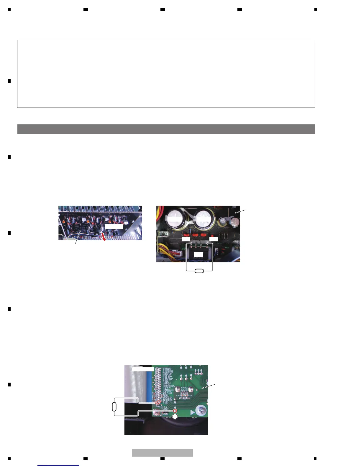
1. Discharging
(1) Unplug the power cord.
(2) Disconnect the 10P connector from CP403 of the AMP Assy between CN3 of the MAIN Assy.
(3) Connect +B and –B terminal of the D7, using resistor leads with 47 - 100 ohms (2 W or higher), for discharging.
∗ Discharging time: 30 - 60 seconds, depending on the level of resistance.
(4) Check that the voltage between the +B and –B terminals is less than 1 V, using a tester.
∗ Be sure to connect the GND terminal of the tester to the chassis.
∗ If the voltage is still 1 V or higher, repeat Step (3).
[1] MAIN Assy Capacitor (C55, C58)
[Procedures]
(1) Unplug the power cord.
(2) Connect CN704A pins 1 or 2 (–30V) of the FRONT Assy and GND terminal A, using resistor leads
with 47-100 ohms (2 W or higher), for discharging.
∗ Discharging time: 5 - 10 seconds, depending on the level of resistance.
(3) Check that the voltage between the –30V terminal is less than 1 V, using a tester.
∗ Be sure to connect the GND terminal of the tester to the chassis.
∗ If the voltage is still 1 V or higher, repeat Step (2).
[2] FL-30 V Capacitor
[Procedures]
47 - 100 ohms
(2 W or higher)
47 - 100 ohms
(2 W or higher)
C55
+B–B
D7
CN704A
CP403
C58
Note:
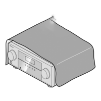
(1) Even if the unit shown in the photos and illustrations in this manual may differ from your product, the
procedures described here are common.
(2) For performing the diagnosis shown below, the following jigs for service is required:
• Board to board extension jig cable (GGD1733)
• Board to board extension jig cable (GGD1734)
• 31P extension jig FFC (GGD1738)
• 9P extension jig cable (GGD1739)
• 13P extension jig cable (GGD1740)
MAIN Assy
AMP Assy
FRONT Assy
A
 Loading...