Do you have a question about the Pioneer VSX-C100 and is the answer not in the manual?
| Type | Stereo Receiver |
|---|---|
| Channels | 2 |
| Frequency Response | 20 Hz - 20 kHz |
| Output Power per Channel | 50W |
| Input Sensitivity | 200 mV |
Key safety checks and precautions for service technicians and customers.
Details on special safety characteristics of components and replacement parts.
Adherence to regulations and safety instructions during servicing.
Optimum adjustments and specification confirmations for original performance.
Proper cleaning of optical pickups, heads, and other parts for performance restoration.
Setting shipping mode or installing screws to prevent transit damage.
Proper application of lubricants/glues and use of prescribed replacement parts/tools.
Details on continuous power output, RMS output, input/output levels, and S/N ratio.
Specifications for frequency range, sensitivity, selectivity, and stereo separation.
Specifications for frequency range, sensitivity, selectivity, and S/N ratio.
Details on power requirements, consumption, dimensions, and weight.
List of parts included with the product, such as antennas and power cord.
Diagram and list of parts included in the product packaging.
Diagram illustrating the main functional blocks and their interconnections.
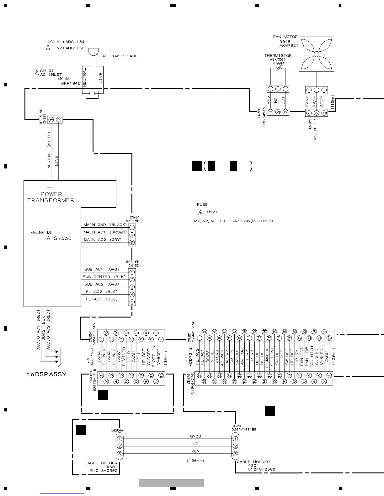
Schematic diagrams for various assemblies like Tuner, DSP, Power, Video.
List of main circuit board assemblies and their part numbers.
Lists of common electronic components and their part numbers.
Indicates that there is no adjustment required for the AM tuner section.
Procedure for adjusting the FM tuner using test equipment and signal conditions.
Details on entering, operating, and exiting various test modes.
Details on DC abnormality, overload detection, and DSP overload specifications.
How temperature affects fan speed, operation, and abnormality detection.
Procedures for detecting fan and thermistor abnormalities and system response.
Explains the purpose and methods for automatically detecting connected speakers.
Details speaker settings based on detection results and the detection circuit.
Description of circuits protecting against speaker overload and DC terminal voltage.
Explanation of the fan detection circuit and its interaction with the microcomputer.
List of integrated circuits used in the product, with part numbers and pin assignments.
Information about the FL display, grid, and segment assignments.
Details pin connections and grid layout for the front panel FL display.
Defines the segment designations for the FL display.
Description of front panel buttons like Power, Phones, Input, and indicators.
Explanation of tuner, display, format, and other indicators and display functions.
Functions of the Receiver (Power) and Signal Select buttons.
Controls for input selection, listening modes, and advanced settings.
Functions of setup, volume, mute, and other system control buttons.
Use of number buttons, channel controls, and understanding the LED indicator.
Operations for menus, navigation, and subtitle control.
Controlling components, searching stations, and broadcast class selection.
Dedicated TV controls and special functions like MPX and D. ACCESS.