6. ADJUSTMENT
MPX SG FM SG
PRODUCT
DC
Voltmeter
L201
IC201
pin 21
pin 23
FM/AM TUNER MODULE
U
SIDE B
Step
No.
Adjustment
Title
ANT. Input level and signal condition
Adjustment
Input Level
(dBµV)
Adjust
point
Contents
Frequency
(MHz)
Modulation
1
T-METER
Adjustment
98 OFF 80
L201
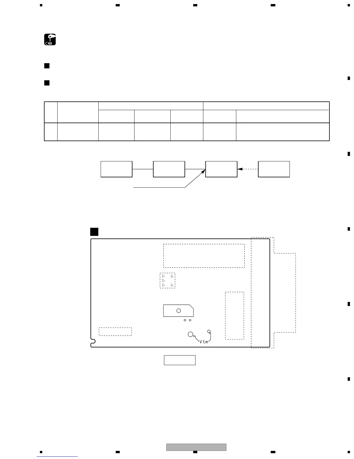
Adjust L201 so that the DC voltage between
Pin 21 and Pin 23 of IC201 (Test point Vtm)
gets within 0 ± 50mV.
AM Tuner Section
• There is no adjustment in the AM tuner.
FM75Ω antenna terminal
Fig.1 Adjustment Wiring Diagram
Notice) Even if it removes TUNER, other functions operate.
Fig.2 Adjustment Point
FM Tuner Section
• Set the mode selector to FM BAND.
• Connect the wiring as shown in Fig. 1.
 Loading...