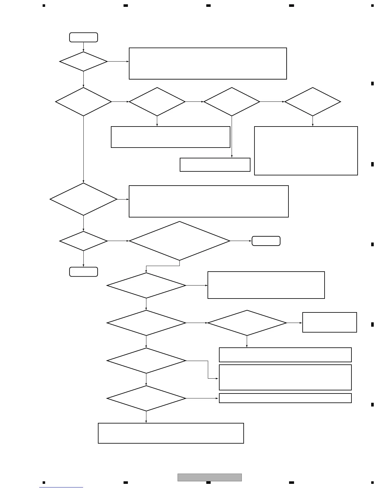
START
Yes
NO
• Check the connection (FRONTAssy - POWER Assy)
• Check each voltages of V+5R6, AC1, AC2 and V-FL (FRONT Assy)
• Check the oscillation of X4201 (FRONT Assy)
• Check ACWP signal (FRONT Assy: pin 4 of IC4201)
• Check ACRY signal (POWER Assy: base of Q201)
Is FL turn on ?
OK
Set
NO
5.1 CH output
is OK?
Is not error
message
indicate it ?
AMP ERR
OVERLOAD
indication ?
Check the output of pins
25-31 of IC1101 (DSP Assy)
NO
THDCT NG
indication ?
NO
DSP NG
indication ?
Yes
Yes
Yes
Yes
Check the output of pins
31-36 of IC1409 (DSP Assy)
Check the input of pins
6-15 of IC1409 (DSP Assy)
Yes
Yes
Yes Yes Yes
Are format indicator
(red for input) and
DOLBY DIGITAL LED
lighting?
Check SURROUND: AUTO
Check the indicator of output format
Check the send DVD player setting
NO
• Check the connection (DSP Assy - DIGITAL IN Assy)
• Check the send DVD player setting
• Check the voltage of IC1101(DSP Assy)
• Is the switch of analog / digital signal becoming with digital or AUTO?
• Is input switch setting of coax and optical 1 properly ?
NO NO
NO
NO NO
Check the output of pins
3-13 of CN1501 (DSP Assy)
Yes
NO
R317, R318, R357, R358,
R386 (POWER Assy)
Yes
Yes
NO
• Check the control of protection relay
Q387, Q389: (POWER Assy) B= "H"
• Check the voltage of RY301, RY341, RY381 (POWER Assy)
• Check the connection (POWER Assy to DSP Assy)
• Check the voltage of IC301 and IC341
• Is not a SP edge short-circuiting?
• Check the connection
(FRONT Assy - DSP Assy)
• Check the voltage of IC1201 to IC1204 and
IC1208 (DSP Assy)
• Check the oscillation of X1201(DSP Assy)
• Check the following communications:
IC1201 (DSP Assy): pins 8-11, 14-17 and
IC1204 (DSP Assy): pins 21-23, 25-29
• Check each voltages of IC1101 (DSP Assy) (+5V)
• Check the oscillation of X1101 (DSP Assy)
• IC1101 (DSP Assy)
• Check the digital input data and clock (pins 9-13)
Check the outputs and
voltages of IC1301-
IC1303 (DSP Assy).
Check the control lines and voltages of pins 39-41 of
IC1409 (DSP Assy)
Check the voltage and periphery of IC301 and IC341
• Check the outputs of IC1502 and IC1503 (DSP ssy)
• Check the control of AMUTE: Q1503 (DSP Assy)
C= "L"UNMUTE
• Check the output and control of IC1704 (DSP Assy)
• Check thermistor installation
TH9014
 Loading...