4.29
ELECTRONIC FUEL INJECTION
4
12. If it does not read .528 ± .01 volts, loosen the screw holding
the TPS to the throttle body. Rotate TPS until voltmeter
reads .528 ± .01 volts.
13. Retighten TPS mounting screw, and verify the voltage did
not change. If changed, repeat the previous steps.
STEP 2
Establishing correct flow: Now that the zero offset voltage has
been set, you can now set the throttle body to the correct air flow
value.
1. With the voltmeter still attached to the TPS Tester Harness
(PU-47082), turn in the air flow adjustment screw until the
voltmeter reads .735 ± .01 volts. The throttle body is now
adjusted to the correct flow value.
2. Reconnect the TPS harness lead
3. Reinstall throttle cable on throttle cam and install cover.
Adjust cable freeplay.
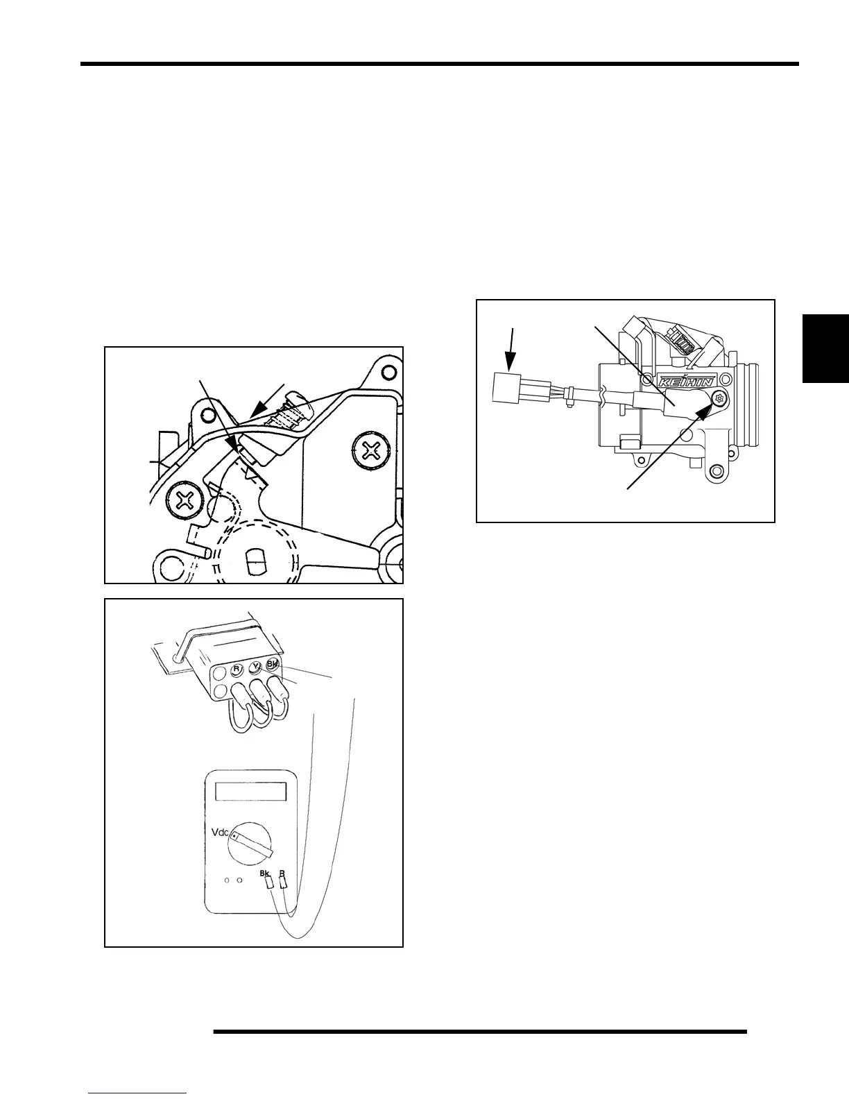
TPS Replacement
NOTE: The correct position of the TPS is
established and set at the factory. Do not loosen the
TPS or alter the mounting position. If the TPS is
repositioned, replaced or loosened it must be re-
calibrated by performing “TPS Initialization.”
1. If the vehicle is completely assembled, remove the exhaust
pipe and exhaust silencer from the vehicle to gain access to
the throttle body and TPS.
2. Disconnect the TPS harness connection (A).
3. Remove the retaining screw (B) and replace the sensor.
4. Refer to “TPS Initialization” for setting the TPS voltage.
Turn Air Flow Screw In
Should Read
.735
Black
Red
Pink
Black
Probe
Red
Probe
.735 Vdc
PU-47082 Tester
TPS
A
B

 Loading...