ELECTRICAL
5.9
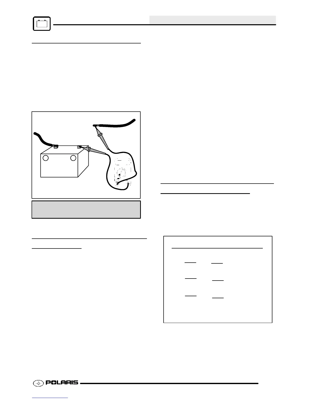
CURRENT DRAW - KEY OFF
CAUTION: Do not connect or disconnect the
batterycableorammeterwith theenginerunning.
Damage will occur to tail light bulb.
Connect an ammeter in series with the negative
battery cable. Check for current draw with the key off.
If the draw is excessive, loads should be
disconnected from the system one by one until the
draw is eliminated. Check component wiring as well
as the component for partial shorts to ground to
eliminate the draw.
Do not use electric start.
--+
Current Draw Inspection
Key Off
Less Than 10 mA
Current Draw - Key Off:
Maximum of .01 DCA (10 mA)
CHARGING SYSTEM “BREAK
EVEN”
TEST
CAUTION: Do not connect or disconnect the battery
cable or ammeter with the engine running.
CAUTION: Never use the electric starter with the
ammeter connected, or damage to the meter or meter
fuse may result. Do not run test for extended period
of time. Do not run test with high amperage
accessories.
The “break even” point of the charging system is the
point at which the alternator overcomes all system
loads (lights, etc.) and begins to charge the battery.
Depending on battery condition and system load, the
break even point may vary slightly. The battery should
be fully charged before performing this test.
G Connect an ammeter (set to DC
amps) in series between the
negative battery cable and terminal.
G Connect a tachometer according to
manufacturer’s instructions.
G With engine off and the key and kill
switch in the ON position, the
ammeter should read negative amps
(battery discharge). Reverse meter
leads if a positive reading is
indicated.
G Start engine with kick start only.
G Increase engine RPM while
observing ammeter and tachometer.
G Note RPM at whichthe batterystarts
to charge (ammeter indication is
positive).
G With any electrical load off, this
should occur at approximately 1500
RPMorlower.
G Lock parking brake to keep brake
light on.
G Repeat test, observing ammeter and
tachometer. With tailllight on,
charging should occur at or below
3000 RPM.
ALTERNATOR OUTPUT TEST
(AC AMPERAGE
TEST)
This test measures AC amperage from the alternator.
G Maximum alternator output will be
indicated on the meter. It is not
necessary to increase engine
RPM above idle.
I = Current in Amps
P = Power in Watts
E = Electromotive Force (Volts)
To Calculate Available Alternator Output:
250W
12V
= 20.8 Amps
I
=
P
E
150W
12V
=
12.5 Amps
I
=
P
E
70W
12V
=
5.8 Amps
I
=
P
E
G Place the red lead on the tester in the
10A jack.
G Turn the selector dial to the AC amps
(Aµ) position.
Enfocus Software - Customer Support

 Loading...