. . © 2012 Proceq SA20 Operation
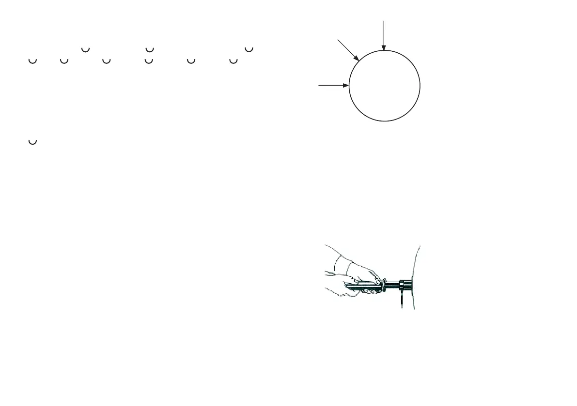
0°
45°
90°
Fig. 51
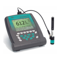
The selected impact direction must be set according
to the measuring situation on the PAROTESTER2
electronic system ( section 6.3.1, Fig.14)
Recommendation: The rolls are measured from left to
right at a distance of 5 cm
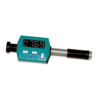
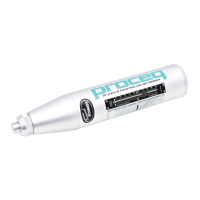
1. Position the impact device vertically to the test surface
Fig. 52
Example:
# Date/time
roll number, , impact device type, , SR,
, U0, , value, , value, , value, , value, , CR,LF
Character definition:
CR = carriage return
ASCII number ( dec. ) = 13
LF = line feed (new line)
ASCII number ( dec. ) = 10
= space
ASCII number ( dec. ) = 32
SR = impact direction number: 1 = down /
2 = 45° - down / 3 = horizontal
U0 = no conversion
8. Operation
8.1 General
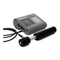
PAROTESTER impact devices and display device are
measuring instruments and must be treated as such.
PAROTESTER2 can be used in three impact directions.
Refer to Fig. 51.
 Loading...