LPWA Module Series
BG95&BG96 Compatible Design
BG95&BG96_Compatible_Design 30 / 47
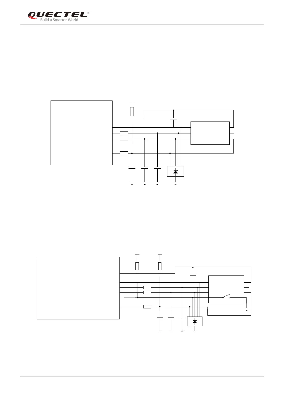
4.7. (U)SIM Interface
BG95 and BG96 support one (U)SIM interface that can meets ETSI and IMT-2000 requirements. BG96
supports 1.8V/3.0V (U)SIM card, but BG95 only supports 1.8V (U)SIM card.
The following figure shows a reference design for (U)SIM interface with a 6-pin (U)SIM card connector.
0R
0R
0R
100nF
(U)SIM Card Connector
GND
ESD
33pF 33pF 33pF
VCC
RST
CLK IO
VPP
GND
GND
15K
USIM_VDD
USIM_GND
BG95/BG96
USIM_VDD
USIM_RST
USIM_CLK
USIM_DATA
Figure 13: Reference Circuit of (U)SIM Interface with a 6-Pin (U)SIM Card Connector
If (U)SIM card detection function needs to be used, please keep USIM_DET/USIM_PRESENCE
connected. The following figure shows a reference design for (U)SIM interface with (U)SIM card detection
function.
USIM_GND
USIM_DET (BG95)
USIM_PRESENCE (BG96)
0R
0R
0R
VDD_EXT
51K
100nF
(U)SIM Card Connector
GND
GND
ESD
33pF 33pF 33pF
VCC
RST
CLK
IO
VPP
GND
GND
USIM_VDD
15K
BG95/BG96 Module
USIM_VDD
USIM_RST
USIM_CLK
USIM_DATA
Figure 14: Reference Design of (U)SIM Card Interface with (U)SIM Card Detection

 Loading...


