LPWA Module Series
BG95&BG96 Compatible Design
BG95&BG96_Compatible_Design 36 / 47
4.13. GRFC Interfaces*
As compared with BG96, BG95 additionally provides two general RF control interfaces for the control of
external antenna tuners.
For more details about the GRFC interfaces of BG95, please refer to document [2].
“*” means under development.
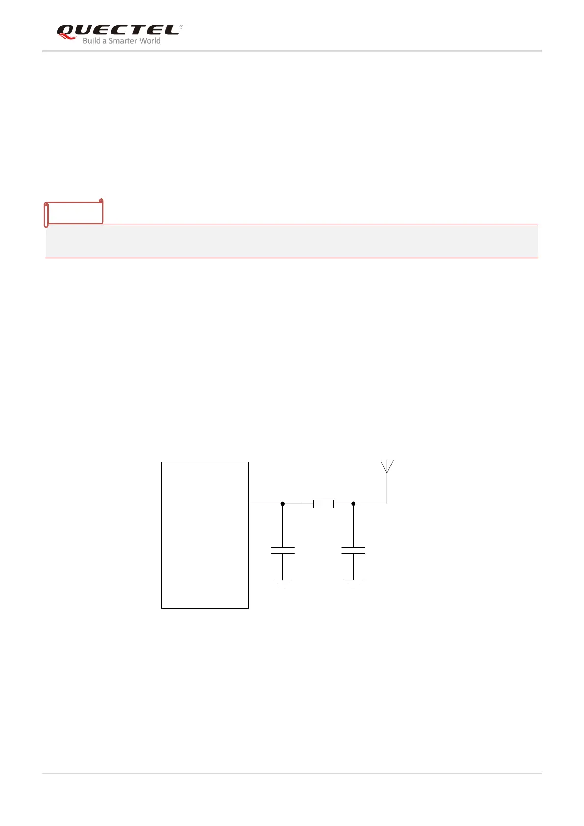
4.14. RF Antenna Interfaces
BG95/BG96 contains two RF antenna interfaces: ANT_MAIN and ANT_GNSS. The RF antenna ports has
an impedance of 50Ω. In order to achieve better RF performance, a π-type matching circuit is
recommended to be reserved, and π-type matching components (R1/C1/C2) should be placed as close
the antenna as possible. By default, the resistance of R1 is 0Ω, and capacitors C1 & C2 are not mounted.
A reference circuit for the interface is shown below.
ANT_MAIN
R1 0R
C1
Module
Main
antenna
NM
C2
NM
Figure 20: Reference Circuit of RF Interfaces
BG95/BG96 supports GNSS function through ANT_GNSS interface. A reference design for ANT_GNSS
antenna interface of BG95/BG96 is shown as below.

 Loading...


