Smart Module Series
SC200R&SC262R_Series_Hardware_Design 53 / 124
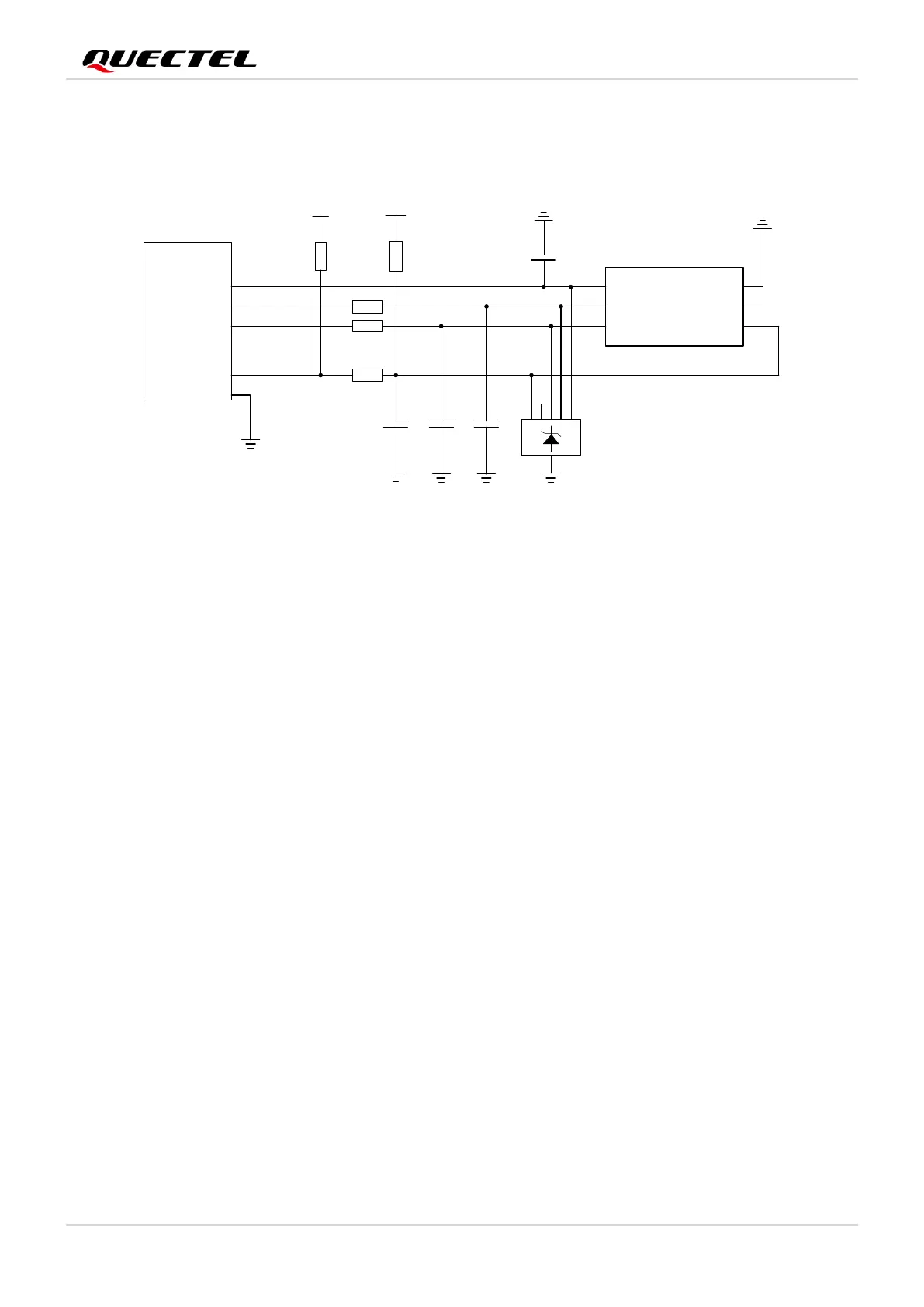
If you do not need to use USIM_DET, keep this pin open. The following is a reference circuit for (U)SIM
interface with a 6-pin (U)SIM card connector.
Figure 16: Reference Circuit for (U)SIM Interface with a 6-pin (U)SIM Card Connector
In order to ensure good performance and avoid damage of (U)SIM cards, follow the criteria listed below
during (U)SIM circuit design:
⚫ Place the (U)SIM card connector as close to the module as possible. Keep the trace length of (U)SIM
card signals as less than 200 mm as possible.
⚫ Keep (U)SIM card signals away from RF and VBAT traces.
⚫ Reserve a filter capacitor for USIM_VDD, and its maximum capacitance should not exceed 1 μF.
Additionally, place the capacitor near the (U)SIM card connector.
⚫ To avoid cross-talk between USIM_DATA and USIM_CLK, keep them away from each other and
shield them with ground. USIM_RST also needs ground protection.
⚫ In order to ensure good ESD protection, it is recommended to add a TVS diode array with parasitic
capacitance not exceeding 50 pF. Add 22 Ω resistors in series between the module and (U)SIM card
to suppress EMI spurious transmission and enhance ESD protection. Please note that the (U)SIM
peripheral circuit should be close to the (U)SIM card connector.
⚫ Add 22 pF capacitors in parallel on USIM_DATA, USIM_CLK and USIM_RST signal lines to filter RF
interference, and place them as close to the (U)SIM card connector as possible.
⚫ Place the reserved pull-up resistors R6 and R5 in Figure 16 and 17 close to the module.
 Loading...


