EasyManuals Logo
Home>Quectel>Control Unit>SC262R Series

Quectel SC262R Series User Manual

Quectel SC262R Series
127 pages
To Next Page IconTo Next Page
To Previous Page IconTo Previous Page
Page #51 background imageLoading...
Page #51 background image
Smart Module Series
SC200R&SC262R_Series_Hardware_Design 50 / 124
3.10. UART Interfaces
SC200R series module provides three UART interfaces and supports up to 4 Mbps:
UART5: 4-wire UART interface, and hardware flow control is supported
UART2 (debug UART): 2-wire UART interface, used for debugging by default
UART1: 2-wire UART interface
Table 14: Pin Definition of UART Interfaces
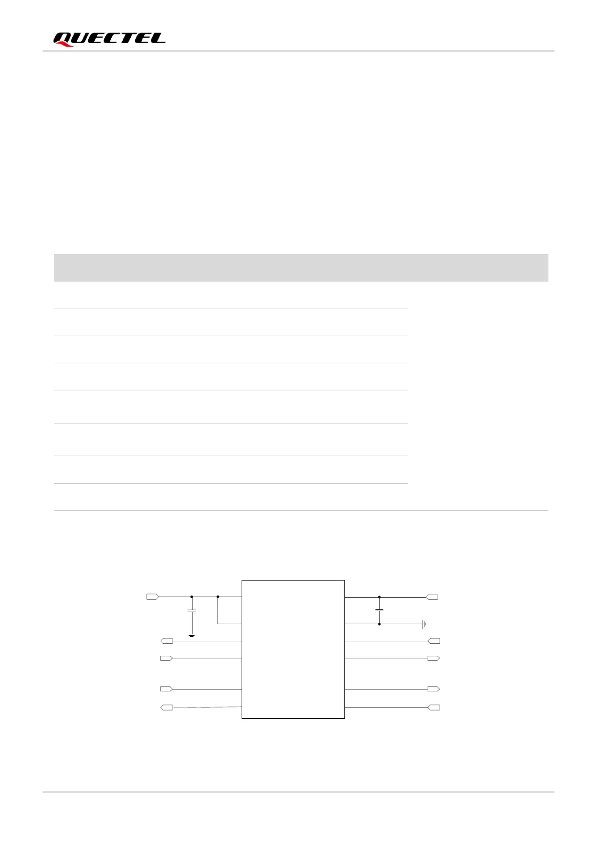
UART5 is a 4-wire UART interface with 1.8 V power domain. You should use a level translator if your
application is equipped with a 3.3 V UART interface. The following figure shows the reference design.
VCCA VCCB
OE
A1
A2
A3
A4
GND
B1
B2
B3
B4
LDO5_1V8
UART5_RTS
UART5_RXD
UART5_CTS
UART5_TXD
RTS_3.3V
RXD_3.3V
CTS_3.3V
TXD_3.3V
VDD_3.3V
C1
100 pF
C2
U1
100 pF
Figure 13: Reference Circuit with Level Translator Chip (for UART5)
Pin Name
Pin No.
I/O
Description
Comment
UART5_TXD
34
DO
UART5 transmit
1.8 V power domain.
If not used, keep these pins
open.
UART5_RXD
35
DI
UART5 receive
UART5_CTS
36
DI
UART5 clear to send
UART5_RTS
37
DO
UART5 request to send
DBG_RXD
93
DI
UART2 receive
(debug UART by default)
DBG_TXD
94
DO
UART2 transmit
(debug UART by default)
UART1_RXD
153
DI
UART1 receive
UART1_TXD
154
DO
UART1 transmit

Table of Contents

Questions and Answers:

Question and Answer IconNeed help?

Do you have a question about the Quectel SC262R Series and is the answer not in the manual?

Quectel SC262R Series Specifications

General IconGeneral
BrandQuectel
ModelSC262R Series
CategoryControl Unit
LanguageEnglish

Related product manuals