Smart Module Series
SC200R&SC262R_Series_Hardware_Design 87 / 124
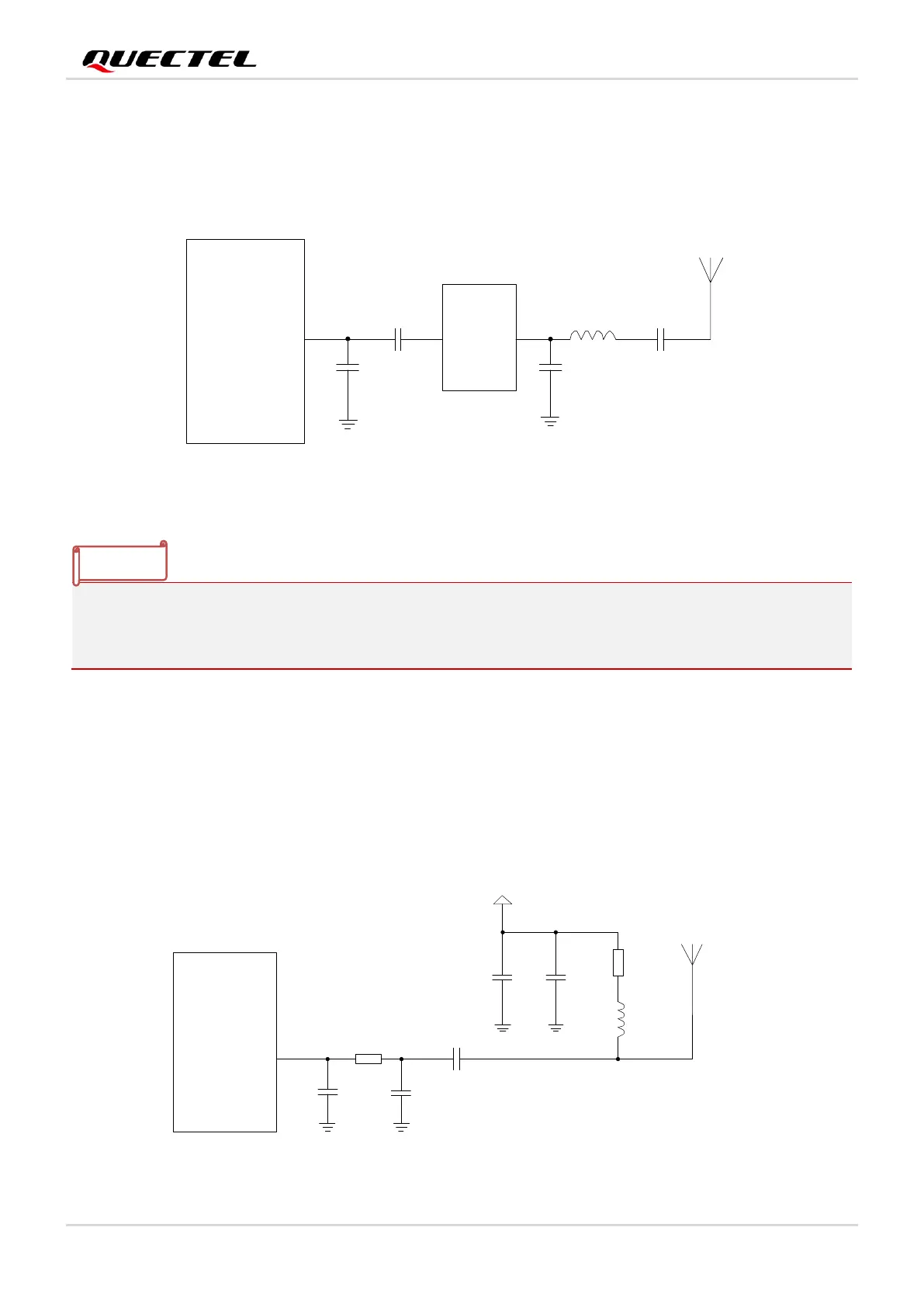
6.3.1. Recommended Circuit for Passive Antenna
GNSS antenna interface supports passive ceramic antennas and other types of passive antennas. A
reference circuit design is given below.
LNA
Passive
Antenna
Module
ANT_GNSS
NM
C1
C2
L1
U1
C3
C4
NM
Figure 31: Reference Circuit Design for GNSS Passive Antenna
When the passive antenna is placed far away from the module (that is, the antenna trace is long) and the
external loss is more than 2 dB, it is recommended to add an external LNA circuit for better GNSS
receiving performance, and place the LNA close to the antenna.
6.3.2. Recommended Circuit for Active Antenna
The active antenna is powered by a 56 nH inductor through the antenna's signal path. The common
power supply voltage ranges from 3.3 V to 5.0 V. Despite its low power consumption, the active antenna
still requires stable and clean power supplies. Therefore, it is recommended to use high-performance
LDO as the power supply. A reference design for GNSS active antenna is shown below.
Active Antenna
VCC
Module
ANT_GNSS
56 nH
10R
1 μF
100 pF
NM
NM
C4
C1
R1
L1
R2
0R
C5
C3
C2
100 pF
Figure 32: Reference Circuit Design for GNSS Active Antenna
 Loading...


