- 31 - V-09 05/2014
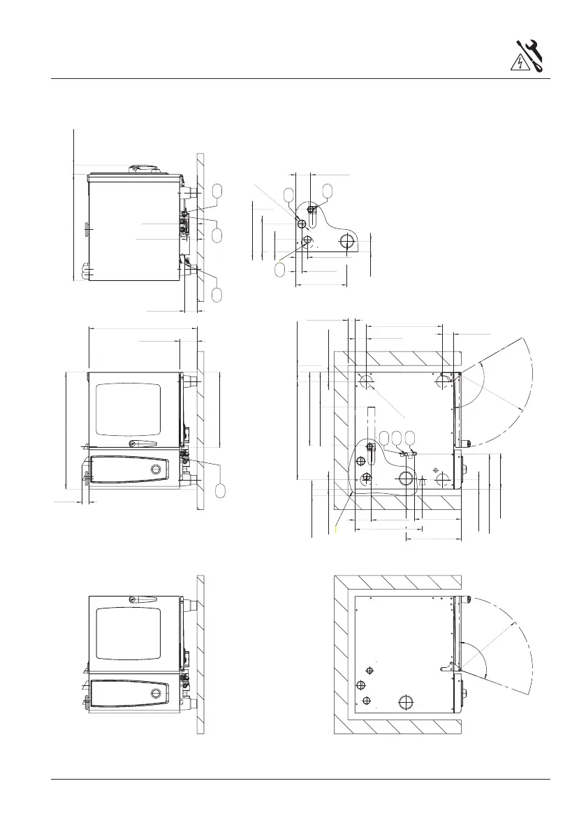
Schematic drawing 6x1/1 GN Gas
n
88
[
3-1/2
]
110
~
R
531
[
20-7/8
]
782
[
30-3/4
]
125
[
4-7/8
]
50
[
2
]
845
[
33-1/4
]
770
[
30-3/8
]
72 [2-7/8]
88 [3-1/2]
67
[
2-5/8
]
711
[
28
]
67
[
2-5/8
]
530
[
21
]
120
[
4-3/4
]
370
[
14-5/8
]
340 [13-3/8]
400
[
15-3/4
]
2515 [-7/8]
256
[
10
]
552
[
21-3/4
]
83
[
3-1/4
]
80
[
3-1/8
]
120
~
R
531
[
20-7/8
]
544
[
21-3/8
]
67
[
2-5/8
]
n
50
[
2
]
n
50
[
2
]
n
50
[
2
]
2015
[
8
]
43
[
1-3/4
]
77
[
3
]
n
603 [2-3/8]
488
[
1-1/4
]
88
[
3-1/2
]
675 [2-5/8]
8
[
3-1/2
]
308 [12-1/8]
107
[
4-1/4
]
845 [3-3/8]
250
[
-7/8
]
n
nnn n
110
nn
n
6
1
2
3
4
5
8
7
10
1 = Common water supply (cold water)
(standard as shipped)
2 = Water supply, cold water*
3 = Water supply, soft water*
4 = Drain, 5 = Electrical connection
6 = Earth bonding, 7 = Venting pipe 2 3/8"
8 = Gas supply 3/4”
9 = Exhaust pipe steam
10 = Exhaust pipe hot air
Measures in mm (inch)
*= option after removal of T-connection
 Loading...