- 41 - V-09 05/2014
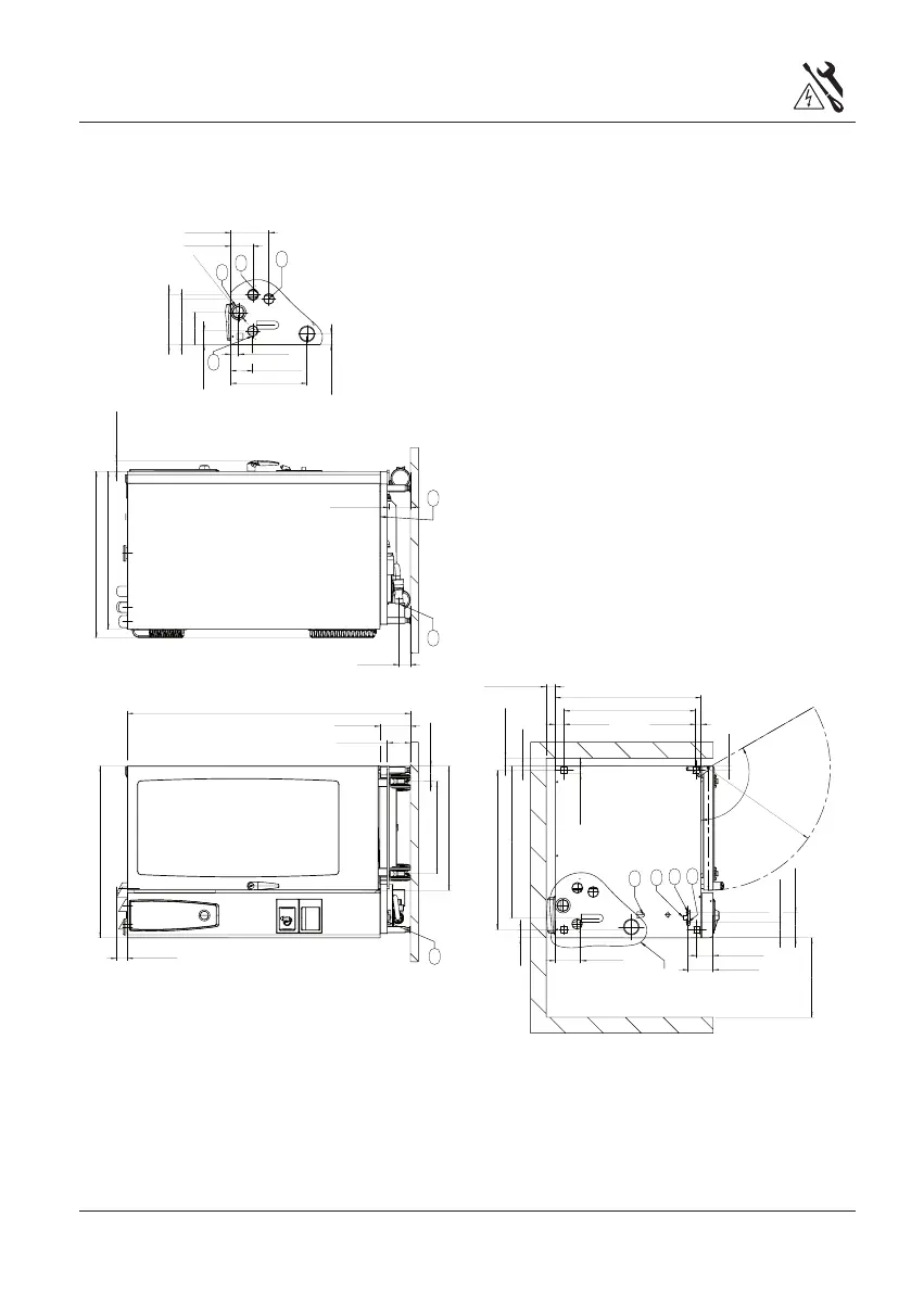
Schematic drawing 20x2/1 GN Gas
o
40
[
1-5/8
]
1782
[
70-1/8
]
190
[
7-1/2
]
68
[
2-5/8
]
1082
[
42-5/8
]
995
[
39-1/8
]
136,5 [5-3/8]
71 [2-3/4]
67
[
2-5/8
]
1003
[
39-1/2
]
27
[
1
]
958
[
37-3/4
]
162 [6-3/8]
480
[
18-7/8
]
156
[
6-1/8
]
159
[
6-1/4
]
99
[
3-7/8
]
829
[
32-5/8
]
57
[
2-1/4
]
920
[
36-1/4
]
34
[
1-3/8
]
120
770
[
30-3/8
]
782
[
30-3/4
]
52
[
2
]
500
[
19-5/8
]
50
[
2
]
55
[
2-1/8
]
204
[
8
]
49
[
1-7/8
]
68,5 [2-3/4]
76,3
[
3
]
145
[
5-3/4
]
96
[
3-3/4
]
582
[
22-7/8
]
1047
[
41-1/4
]
25
[
1
]
103,5 [4-1/8]
138,5 [5-1/2]
87
[
3-3/8
]
140
[
5-1/2
]
240
[
9-1/2
]
315
[
12-3/8
]
289
[
11-3/8
]
o
o
o
110
6
1
2
3
8
4
5
7
9
10
10
1 = Common water supply (cold water) (stan-
dard as shipped)
2 = Water supply, cold water*
3 = Water supply, soft water*,
4 = Drain,
5 = Electrical connection,
6 = Earth bonding;
7 = Venting pipe 3"
8 = Gas supply 3/4”,
9 = Exhaust pipe steam
10 = Exhaust pipe hot air
Measures in mm (inch)
*= option after removal of T-connection
 Loading...