- 37 - V-09 05/2014
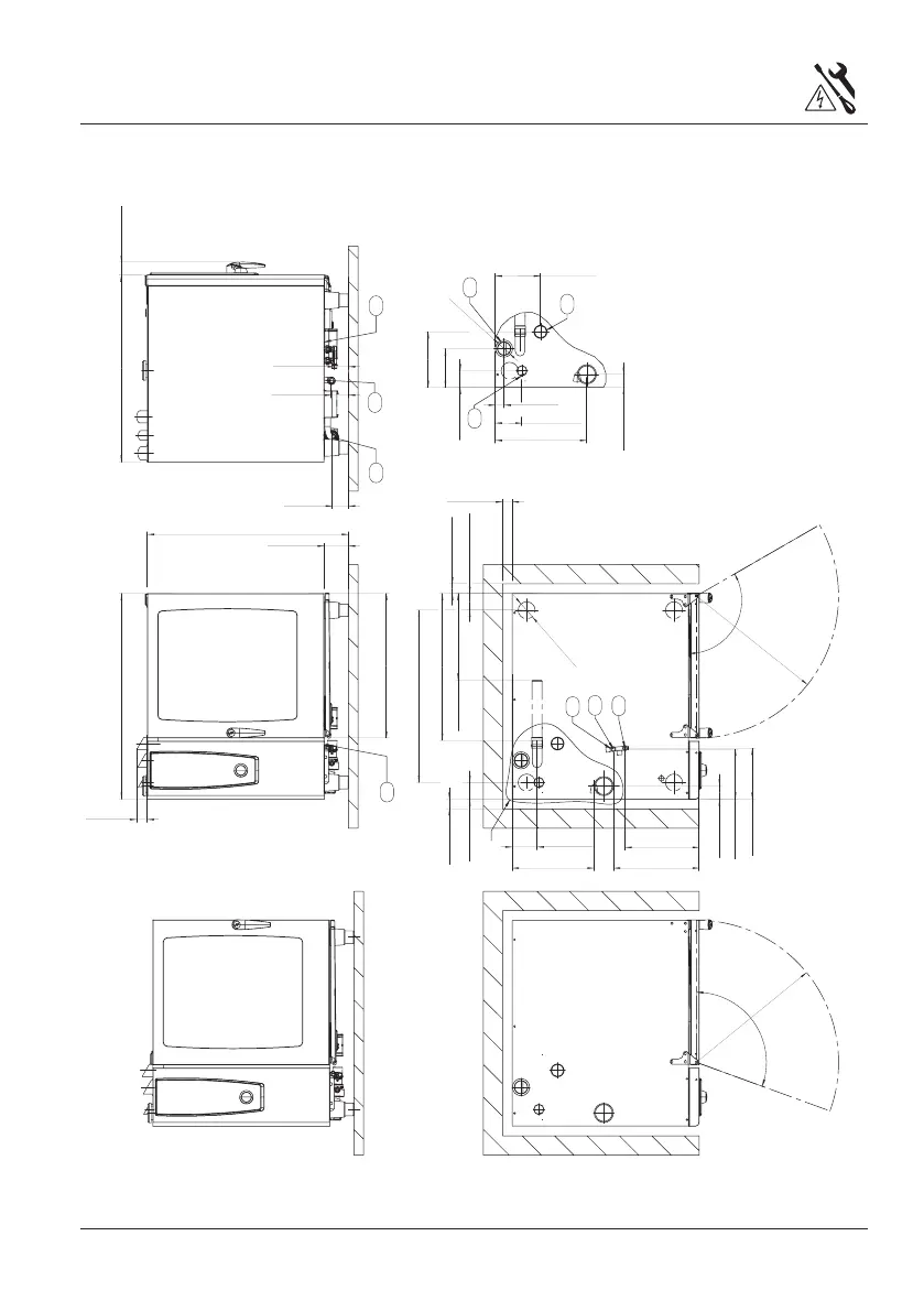
Schematic drawing 10x2/1 GN Gas
n
88
[
3-1/2
]
110
~
R
737
[
29
]
1042
[
41
]
125
[
4-7/8
]
56
[
2-1/4
]
1067
[
42
]
970
[
38-1/4
]
72 [2-7/8]
84 [3-3/8]
67
[
2-5/8
]
893
[
35-1/8
]
87
[
3-3/8
]
761
[
30
]
129
[
5-1/8
]
385 [15-1/8]
445
[
17-1/2
]
260
[
10-1/4
]
265 [10-1/2]
120
~
R
737
[
29
]
749
[
29-1/2
]
87
[
3-3/8
]
n
50
[
2
]
n
50
[
2
]
n
50
[
2
]
202
[
8
]
46
[
1-3/4
]
475
[
18-3/4
]
685 [2-3/4]
n
70
[
2-3/4
]
88
[
3-1/2
]
425
[
16-3/4
]
70
[
2-3/4
]
87
[
3-3/8
]
1385 [5-1/2]
235
[
9-1/4
]
289
[
11-3/8
]
450
[
18
]
n
nnn n
110
nn
n
6
1
2
3
4
5
8
7
9
10
1 = Common water supply (cold water)
(standard as shipped)
2 = Water supply, cold water*
3 = Water supply, soft water*
4 = Drain, 5 = Electrical connection
6 = Earth bonding, 7 = Venting pipe 2 3/4"
8 = Gas supply 3/4”
9 = Exhaust pipe steam
10 = Exhaust pipe hot air
Measures in mm (inch)
*= option after removal of T-connection
 Loading...