Service Manual 7. UHF3 (350-400 MHz) Information
132
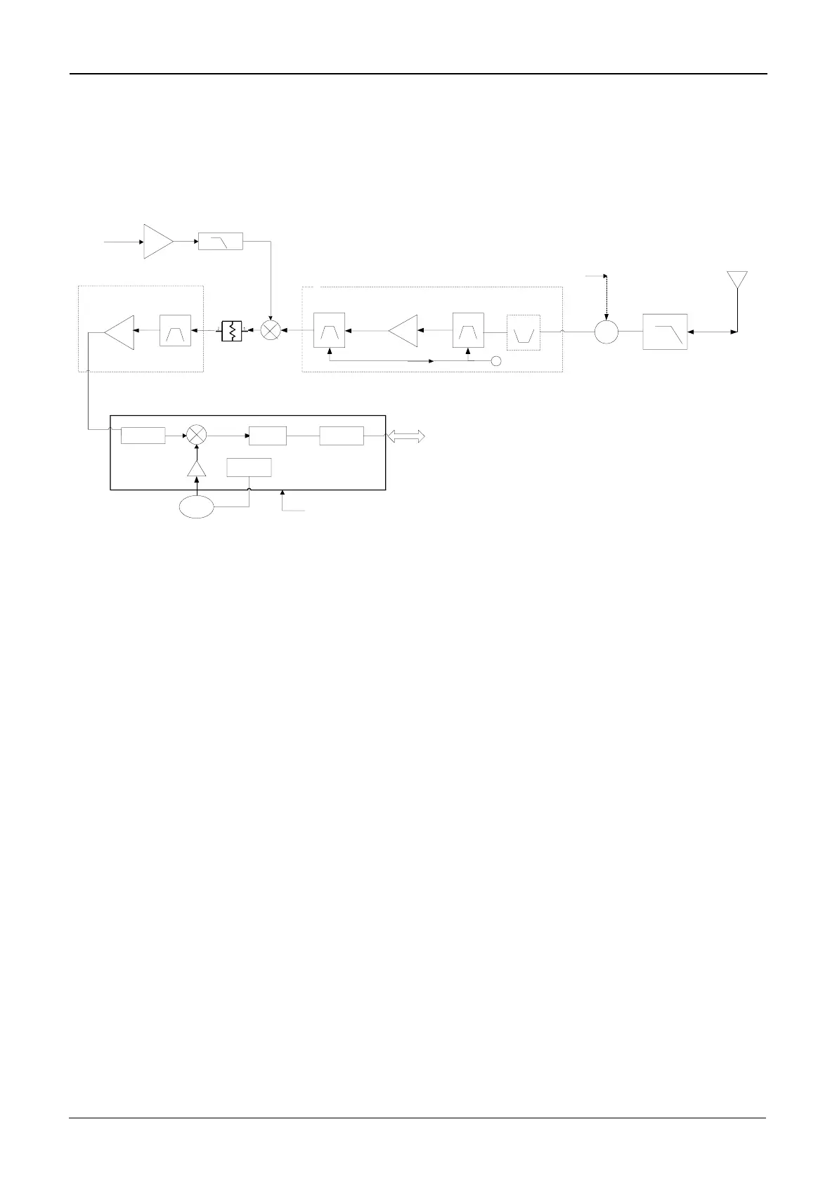
7.2 Receiver Circuit
The receiver circuit is mainly composed of RF band-pass filter, low-noise amplifier, mixer, IF
filter, IF amplifier, and IF processor.
Low-Noise AmpBand-Pass Filter
Mixer
IF Filter
IF Processor
AD9864
IF Amp
TV/APC
To DSP (OMAP)
TX/RX Switch Low-Pass Filter
Band-Pass Filter
FLo
RF
IF
Antenna
TX
ADC
Second
Lo VCO
Synthesizer
19.2 MHz
Reference Clock
-16 dB
Attenuation
Q6002
Low-Pass Filter
D6002
Q6003,Q6004
U6002
U6001
Decimation
Filter
FLO Amp
Q6001
Pi Attenuator
Figure 7-2 Diagram of Receiver Circuit
7.2.1 Receiver Front-End
The HF signal from the low-pass filter passes through the first-level band-pass filter, to
remove out-of-band interference signal and to send wanted band-pass signal to the low-noise
amplifier (Q6002). The amplified signal goes to the second-level band-pass filter, to remove
out-of-band interference signal generated during amplification, and to send wanted HF signal
to the mixer (D6002). In the mixer, the wanted signal and the first LO signal are mixed to
generate the first IF signal (73.35 MHz). Then the signal passes through a π-shaped
attenuator and the LC, to suppress carrier other than the first IF signal, and to increase the
isolation between the mixer and the IF filter. After that, the first IF signal is processed by the
crystal filter (U6001), and is sent to the two-stage IF amplifier circuit (composed of Q6003 and
Q6004) for amplification. Then the amplified signal goes to the IF processor AD9864 (U6002)
for processing.
 Loading...