Service Manual 7. UHF3 (350-400 MHz) Information
134
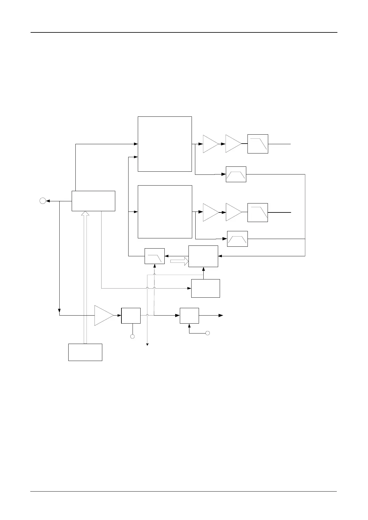
7.3 FGU
The Frequency Generation Unit (FGU) comprises VCO and PLL. It is the core module of the
whole TX-RX system. This circuit provides accurate carrier frequency during transmission,
and stable LO signal during reception. It has a direct influence on the performance of the
system.
TX_VCO
Frequency
Synthesizer
RX_VCO
Ref. Osc
19.2 MHz
MOD-VCO
MOD2+Freq Error Shift
4CH DAC
4-Pole RC Filter
TX VCO
Amplifier
From OMAP
Reference OSC Signal
CV Buffer
Adapt
SW
Adapt
Control
OP
TX VCO
Buffer
LPF
CV
SW
CV-Read
Control
CV OUT
TX VCO
OUTPUT
OMAP
RX VCO
Amplifier
LPF
RX VCO
Buffer
RX BPF
TX BPF
RX VCO
OUTPUT
Figure 7-4 Diagram of FGU
7.3.1 Working Principle of PLL
The 19.2 MHz frequency generated by the reference crystal oscillator goes to PLL for division,
generating the reference frequency (i.e. step frequency f1). Meanwhile, the frequency
generated by VCO generates another frequency (f2) through the frequency divider in PLL.
Then frequencies f1 and f2 are compared in the phase detector (PD), to generate continuous
pulse current. The current goes to the loop filter for RC integration, and is then converted to
 Loading...