Service Manual 3. Baseband Section
12
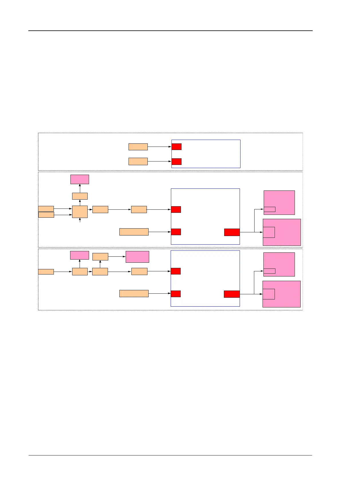
3.2.6 Clock
The system needs three clocks for operation: system clock, clock for RTC on OMAP-L138,
and clock for the control head MCU. The system clock is provided by 19.2 MHz TCXO or an
externally calibrated 19.2 MHz clock source. Clock for RTC on OMAP-L138 is generated by
the 32.768 kHz crystal oscillator. The clock used by the MCU for the control head is provided
from the 12 MHz crystal oscillator. Diagram of clock distribution is shown in Figure 3-5.
OMAP-L138
CLK
32K
32768 Hz
Crystal
32768 Hz
19.2 MHz
TCXO
Buffer
PLL
SKY72310
Audio Codec
TLV320AIC29
MCLK
CLKOUT
19.2 MHz
Noise Reduction IC
BR261W26
19.2 MHz 0.8-1V
19.2 MHz 3.3V
Filter
19.2 MHz <1.2V
19.2 MHz <2V
Filter
Exit CLK
SPDT
External
19.2 MHz
19.2 MHz 0.8-1V
Clock Select Control
OMAP-L138
CLK
32K
Audio Codec
TLV320AIC29
MCLK
CLKOUT
19.2 MHz
Noise Reduction IC
BR261W26
Exit CLK
32768 Hz
Crystal
32768 Hz
Filter
19.2 MHz <1.2V
19.2 MHz
TCXO
Buffer
PLL
SKY72310
19.2 MHz 0.8~1V
19.2 MHz 3.3V
19.2 MHz <2V
Filter
19.2 MHz <3.3V
Filter
IF Processor
AD9864
LPC1774
CLK
32K
32768 Hz
Crystal
32768 Hz
12 MHz
Crystal
12 MHz
Control Head
Transmitter Circuit
Receiver Circuit
Figure 3- 5 Diagram of Clock Distribution
 Loading...