Service Manual 3. Baseband Section
18
3.5 Rear Board
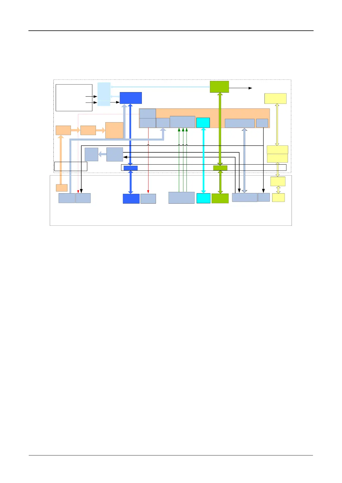
3.5.1 Block Diagram
UART1
PTT
Ethernet
PHY
Ext_Mic
Handset_Audio
RX_Audio
PA_Audio
Repeater Unit
Control IO
DB9
For GPS
PTT1
PTT2
RJ45
Transformer
Ext_Mic1
Slot1_Audio
Slot2/RX_Audio
PA_Audio
DB26
IO Expand
(Programmable IN/OUT)
Lightning
Protection
Rear Board
Fan
Driver
EXT
PWR
FAN
RS232
Ext_Mic2
Ext_Mic
USB0
USB0
UART2
RS232
DB15
For BS Application
CLK_SEL
ALARM_OUT
IGN_IN
SPI
Expand
3GPIO
From
Control Head
MCU
IDC26
IDC10
EXT
PWR
IDC10
5VD
5VD LDO
3.3V
For Rear
Accessory
Board
Figure 3-11 Diagram of Rear Board
3.5.2 Working Principle
The rear board, being the extension board of the repeater unit, comprises the external
connectors as follows:
DB26: This is a 26-pin connector for further development and this connector provides
USB signal, programmable GPIOs, and audio input/output, etc.
DB15: The repeater communicates with other equipment via UART pins on the DB15
connector.
DB9: This connector provides UART, SPI, GPIO, and power signals, and is used to
configure and control the GPS board.
RJ45: PHY signal output from the repeater unit is processed by the transformer and
lightning protection module and then feeds to the RJ45 Ethernet connector on the rear
board for remote diagnosis&upgrade, and data communication.
 Loading...