Service Manual 3. Baseband Section
17
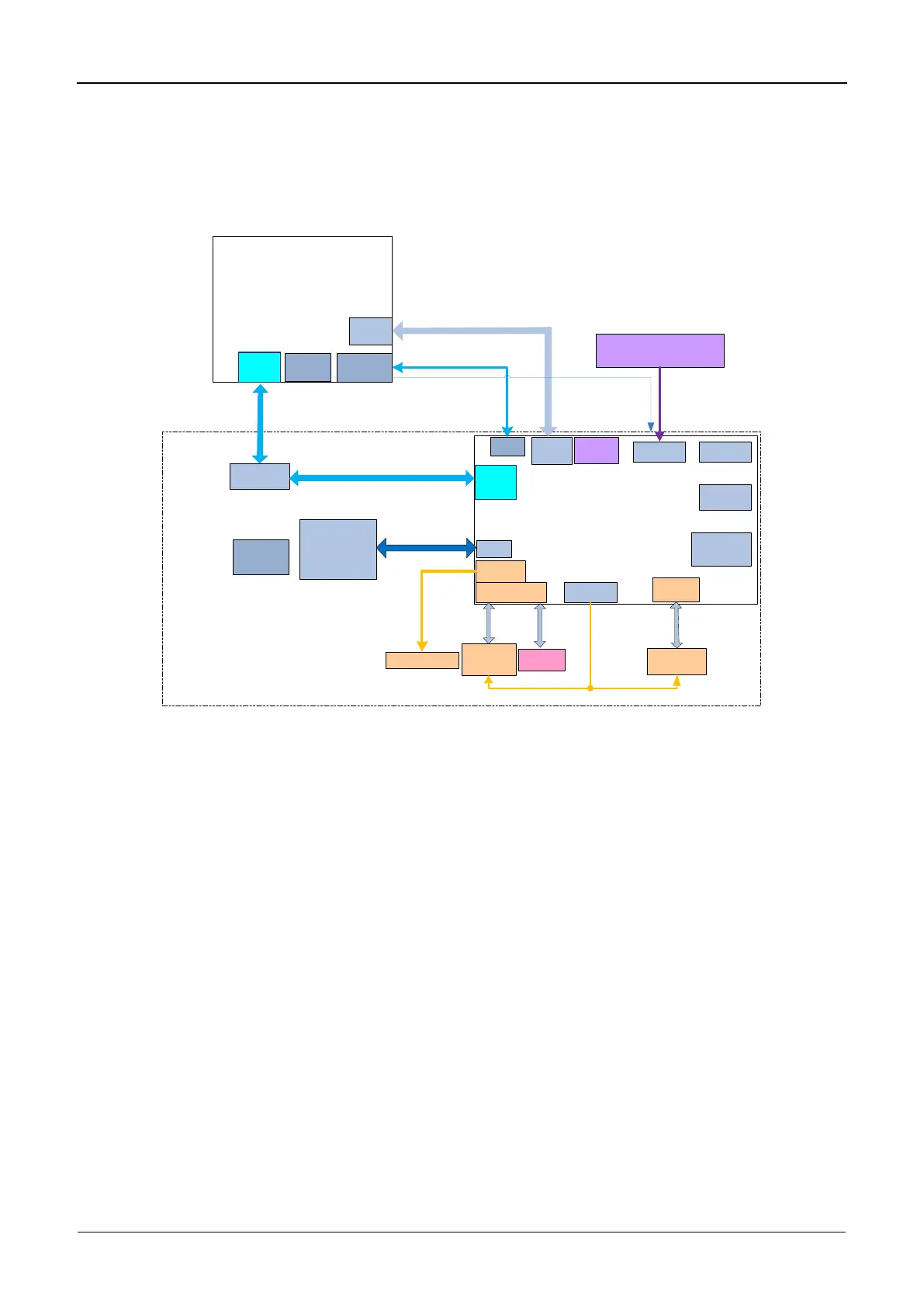
3.4 Control Head
3.4.1 Block Diagram
OMAP-L138
`
UART0
USB0
LCD Backlight
PTT
Control Head MCU
UART1
UART2
TFT2.4
240*320
SDRAM
NOR Flash
Key
Volume Switch
Channel Knob
EMC
Serial
GPIO
Control Head
INT SPK
RSTOUT
SSP1
PWM0[1]
USB1
SPDT
RESET JTAG
12 MHz
CLK
32 kHz
RTC CLK
(reserved)
Reset Signal
From OMAP
MAX803SQ308D2T1G
GPIO
GPIO
Figure 3-10 Diagram of Control Head
3.4.2 Working Principle
The control head processor is an ARM Cortex-M3 LPC1774. It works with a SDRAM memory
and NOR flash memory to control devices and modules on the control head. NOR flash
memory is used to store images, data, and programs. SDRAM memory runs system routine
and stores real-time data. OMAP-L138 shares information on the main CPU with the control
head and controls the latter via the UART interface.
3.4.3 MCU Reset
The MCU will be reset by a dedicated external reset chip and OMAP-L138.
3.4.4 Key and Display Management
MCU uses the GPIO interface to control key operation and connects to the LCM module via
the EMC bus.
 Loading...