RL78/G13 Handshake-based SPI Master Transmission/Reception
R01AN6883EJ0100 Rev.1.00 Page 12 of 38
June.15.23
4. Hardware Descriptions
4.1 Example of Hardware Configuration
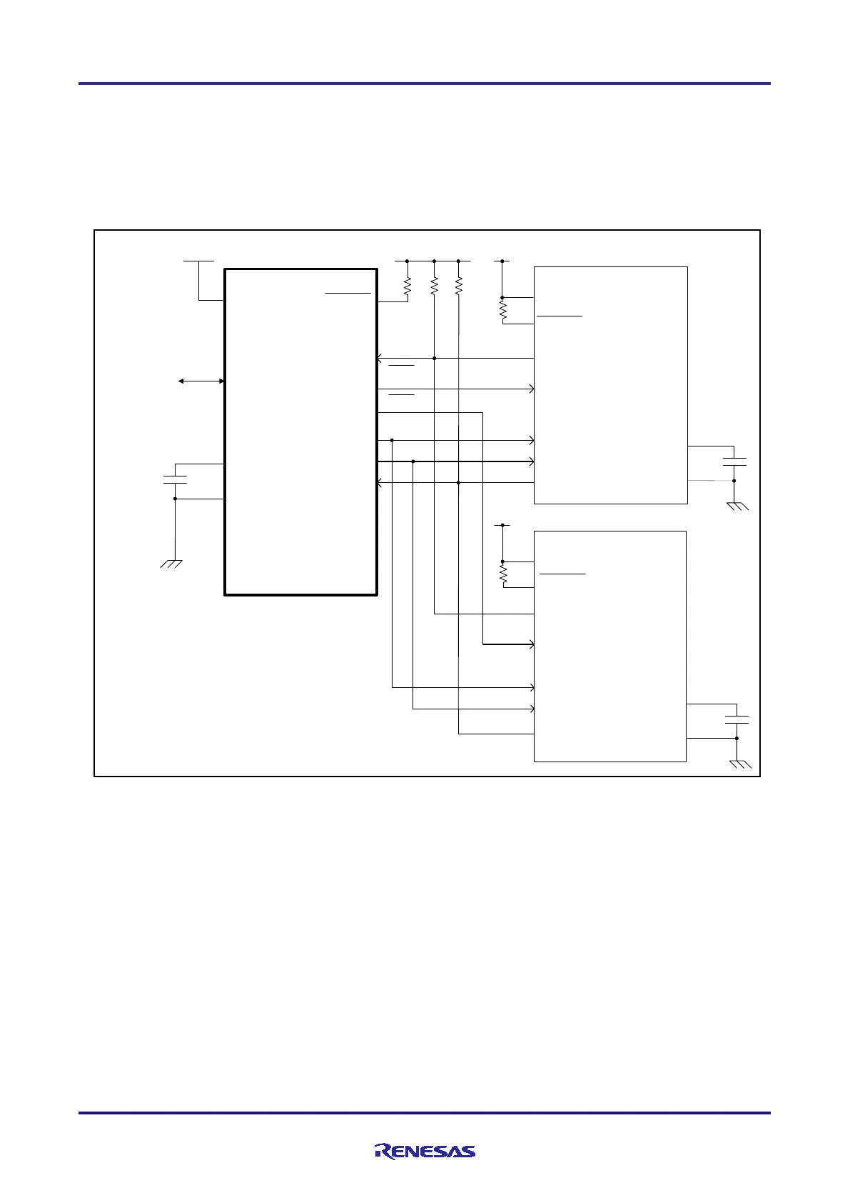
Figure 4-1shows an example of the hardware configuration used in the application note.
Figure 4-1 Hardware Configuration
RESET
P40/TOOL0
V
DD
OCD
RL78/G13
V
DD
/EV
DD
REGC
V
SS
/EV
SS
V
DD
P10/SCK00
P54
P11/SO00
P12/SI00
BUSY
P53
P52
CS1
CS2
RESET
V
DD
RL78/G13
V
DD
/EV
DD
REGC
V
SS
/EV
SS
P00
P137/INTP0
P10/SCK00
P11/SO00
P12/SI00
Master
Slave1
RESET
V
DD
RL78/G13
V
DD
/EV
DD
REGC
V
SS
/EV
SS
P00
P137/INTP0
P10/SCK00
P11/SO00
P12/SI00
Slave2
Note 1. This schematic circuit diagram is simplified to show the outline of connections. When creating
circuits, design them so that they meet electrical characteristics by properly performing pin
processing. (Connect input-only ports to V
DD
or V
SS
individually through a resistor.)
Note 2. Connect pins (with a name beginning with EV
SS
), if any, to V
SS
, and connect pins (with a name
beginning with EV
DD
), if any, to V
DD
.

 Loading...


