RL78/G13 Handshake-based SPI Master Transmission/Reception
R01AN6883EJ0100 Rev.1.00 Page 14 of 38
June.15.23
5. Description of the Software
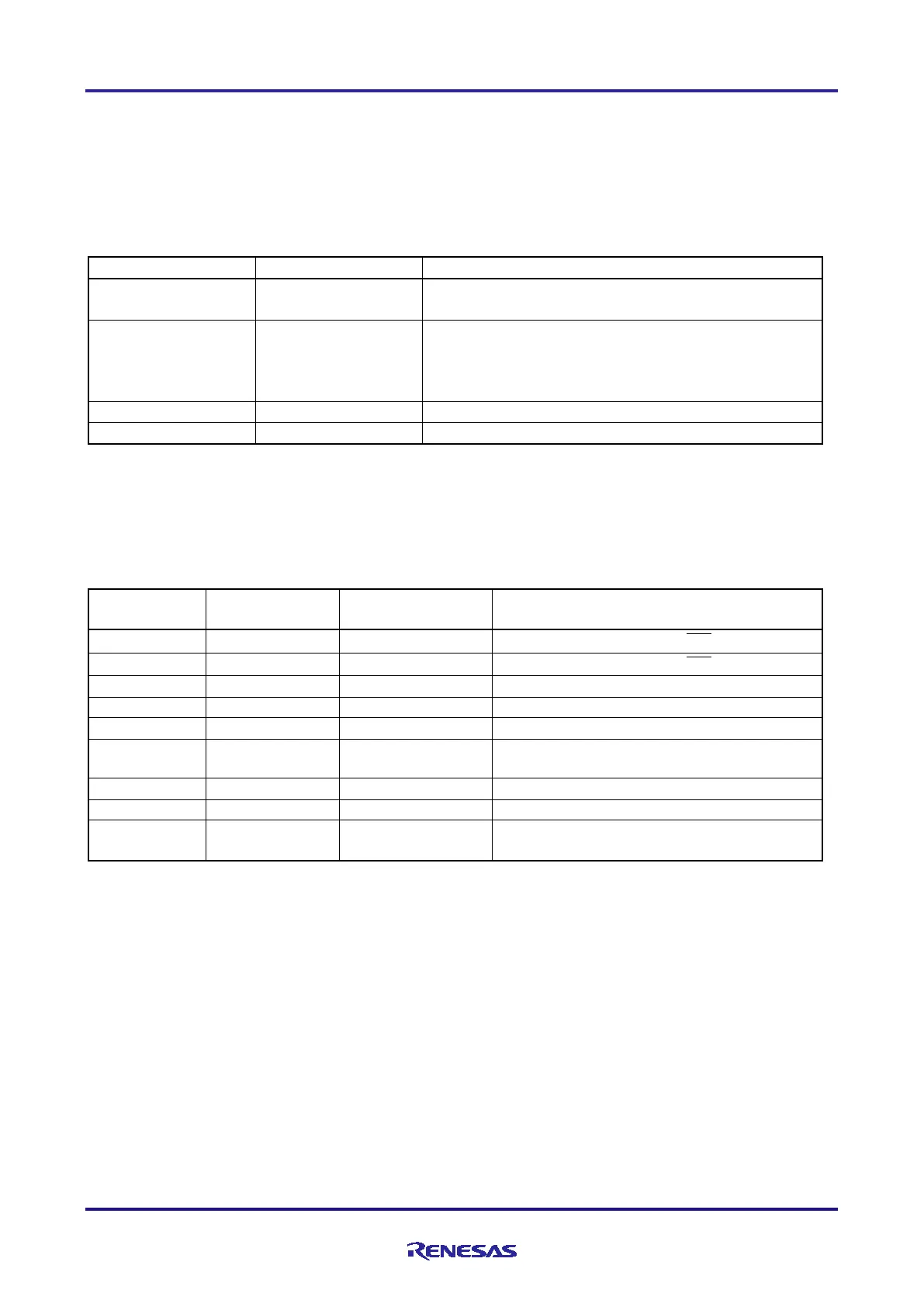
5.1 List of Option Byte Settings
Table 5-1 summarizes the settings of the option bytes.
Table 5-1 Option Byte Settings
5.2 List of Constants
Table 5-2 lists the constants that are used in the sample code.
Table 5-2 Constants Used in the Sample Code
Port register to control the
CS1
Port register to control the
CS2
Port register to detect the BUSY signal
Number of data characters to be transmitted
Number of data characters to be received
Number of data characters to be
transmitted/received
Stores 63 characters of transmit data, the
maximum number of characters transferred.
Notes: 1. For details, see Table 1-4.
2. In this application note, ASCII codes from 0x20 to 0x5F are stored.
Stops the watchdog timer operation.
(Stops counting after the release of the reset state.)
Detection Voltage:
On the rising edge: TYP. 1.88 V
On the falling edge: TYP. 1.84 V
Enables the on-chip debugging function.

 Loading...


