repligen.com IF.UG.028 R1
10. With filter and pump securely in place, install the permeate tubing, making sure there is no
bending or kinking of the permeate tubing. Run extra tubing to the permeate vessel. Make
sure permeate pressure sensor (PE-03) is located between filter housing permeate port and
any valves prior to permeate collection.
11. Locate the clamp-on retentate flowmeter (FL-01) on the filter stand. Install the retentate
tubing in the flowmeter and close the flowmeter clamp. Make sure there is 10 - 15 cm (4” -
6”) of straight run tubing on each side of the meter. The return tubing may need auxiliary
support to prevent kinking. Clamp the meter onto tubing. Note flow direction arrow on
meter should point in up direction.
6.2 Electrical installation
All electrical connections are made with plugs and sockets located on the rear side of the control
panel.
Power requirements for system
200 - 240 VAC, 10/15 Amp Service, single phase.
To complete the system electrical connections:
1. Connect P-01, P-02, and P-03 connectors to panel.
2. Connect flow meter FL-01, FL-02 connectors to the flow meters.
3. Connect three pressure sensor cables (PE-01 feed, PE-02 retentate, PE-03 permeate) to the
flow patch pressure sensors.
4. Connect Main Panel power cord to suitable electrical outlet (200 - 240VAC, 10/15 Amp
Service).
5. Make sure that the Emergency Stop (E-Stop) button is pulled to OUT (inactive) position.
6. Turn on the Main Power by rotating the handle on the front of the control cabinet; this
starts the computer, and the control software loads automatically.
7. Press Reset button (Blue) on Control Panel.
6.3 Ferrite Bead installation
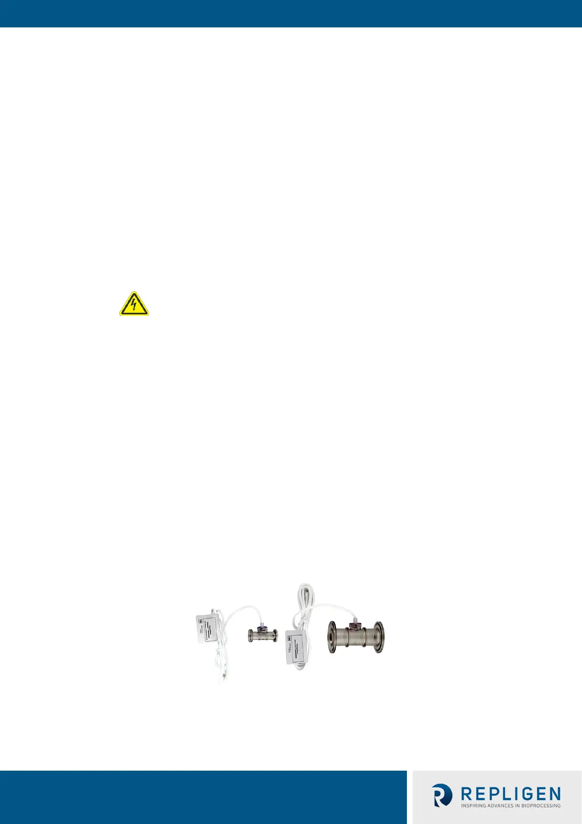
Polysulfone pressure sensors/transmitters are included as part of the sterile disposable ProConnex®
Flow Path (Module Bag Tubing (MBT)) that is shipped with your KrosFlo® KTF System.
Figure 2. Polysulfone pressure sensors example
A ferrite bead (P/N 3000541) is provided for each flow path pressure sensor to protect it against
possible electromagnetic interference (EMI). We recommend that you install the supplied ferrite
bead on each flow path pressure sensor cable to provide EMI protection for the pressure sensor.
WARNING – Do not plug in the system during Electrical Assembly
until instructed.

 Loading...


