NON-COMMUNICATING
CONDENSER UNIT
NON-COMMUNICATING
CONDENSER UNIT
O
O
125 FEET MAX. @ 18 GA.
125 FEET MAX. @ 18 GA.
100
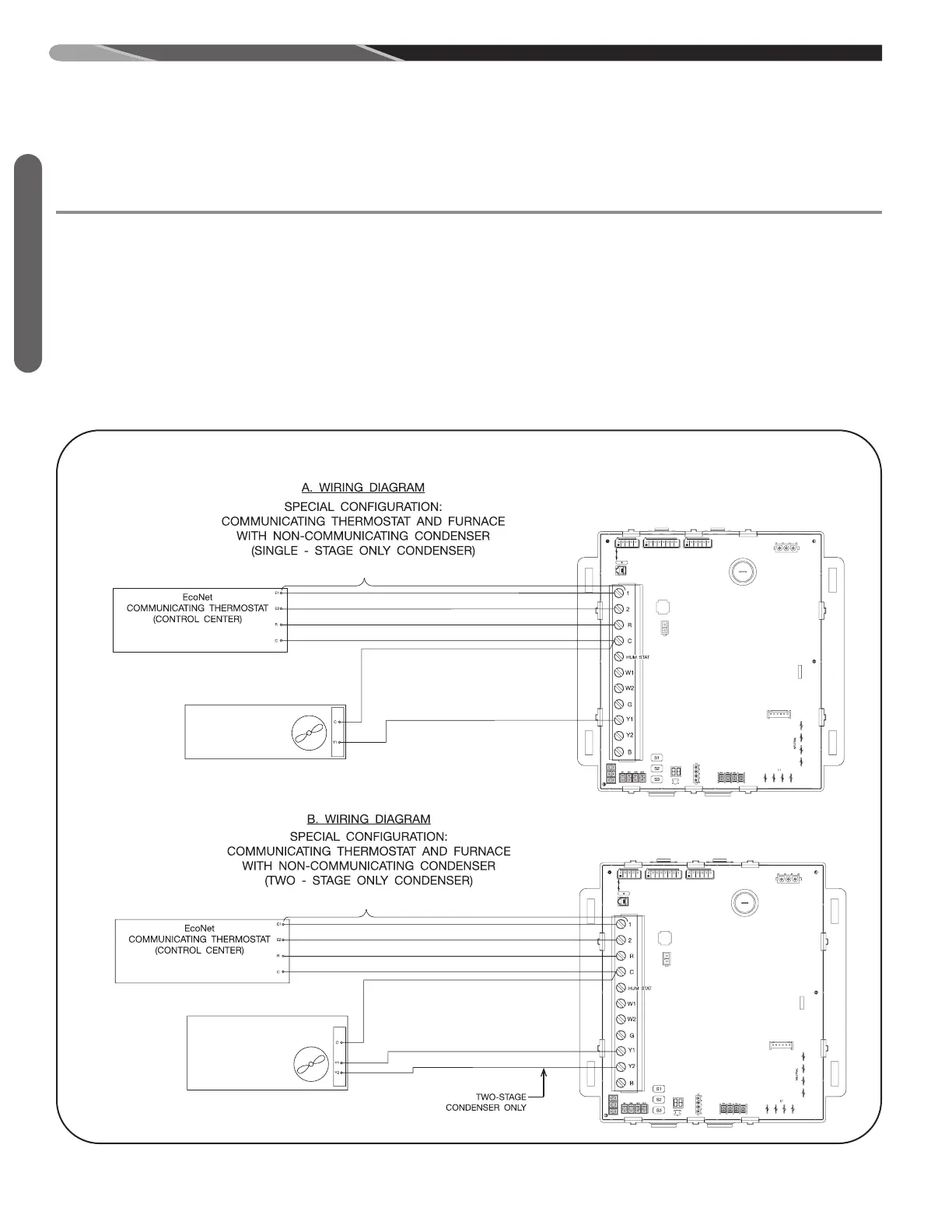
FIGURE 54
WIRING DIAGRAM FOR NON-COMMUNICATING CONDENSER COMMUNICATING FURNACE AND THERMOSTAT.
ST-A1194-54-02
Communicating Furnace
INTE
GRATE
D FURNACE
CONTROL
T
H
E
R
M
O
S
T
A
T
W
I
R
I
N
G
D
I
A
G
R
A
M
S
Figure 53 is the wiring diagram for connecting the furnace
to an approved EcoNet communicating thermostat and ap-
proved EcoNet communicating condenser. The only ap-
proved configuration is to install dedicated wires directly
from the furnace to the thermostat and a separate set of
dedicated wires directly from the furnace to the condenser.
Additional EcoNet devices can be added to the system as
shown in Figure 53. The approved wiring configuration is
the daisy-chain configuration shown in Figure 53. A star
wiring configuration is not approved and should not be
used.
Note: The only approved configuration requires that four
dedicated wires (E1,E 2, R and C) be installed from the
furnace to the condenser.
A2. SPECIAL CONFIGURATION – WIRING OF
NON COMMUNICATING CONDENSER
UNITS WITH COMMUNICATING FURNACE
AND THERMOSTAT (SEE FIGURE 54).
 Loading...